ANALOG ELECTRONIC (FET) Determine the operating point of the amplifier by finding I(DQ) and V(GSQ) using the graphical method.
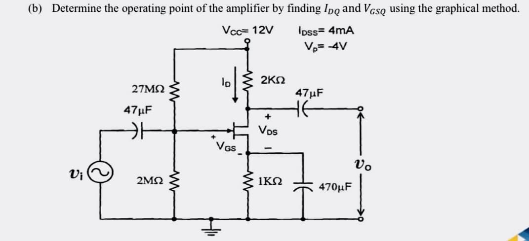
Q: For a balanced Y-Y three phase system, the time domain expression for the phase-a line to neutral…
A:
Q: Q2- In the circuit in fig.(2) if 13= 1mA. Find all currents (11, 12, 14 and 15) and the voltage…
A: In this question, We need to determine the unknown currents, and voltage Vs? We are solving this…
Q: P.3. R₂ M 200 V C At t = 0, the switch is closed. The initial energy stored in the inductor and the…
A:
Q: what are the circui JAU
A:
Q: IS 19 load at power factor of 0.9 and efficiency o 28%. find the quality of cooling air required.…
A: Given,P = 4.2 MVAPOWER FACTOR = 0.9P= 0.9×4.2 = 3.78 MWEfficiency = 28%losses dissipated =…
Q: An ECM involving the installation of high efficiency light fixtures without changing lighting…
A: Given: An ECM involving the installation of high-efficiency light fixtures without changing the…
Q: A non-reactive resistance of 60 Ω is connected in series with a 36 µF capacitor in each phase of a…
A:
Q: PROBLEM2-PART1 Evaluate the convolution of the shown signals. h(n) 0 1 2 3 4 x(n) 1. 2
A: In this question we need to find a convolution of the given signal.
Q: Q4: Find Vx in the network in fig.(4) using mesh (loop) analysis. 12^ M m 30v vx=4r {4^ Fig.4 Elon…
A:
Q: Q1/- For the shown waveform: 1- Write the equation of the signal e (t). 2- Plot the spectrum of the…
A:
Q: Q3: Find Req. between points (A&B) in the network in fig.(3). 2 lon 8.r 36₁ B
A:
Q: If a Si diode at room temperature (25°) has a leakage current Is = 46 nA, k = 5,800, and V₁ = 0.65…
A: We are authorized to answer one question at a time, since you have not mentioned which question you…
Q: 2 A C₁ C₂ = C3 = 2mF C4 C₁ = Cs = Gc = 4μF N VAB = 10V A) CTOTAL - B) Q TOTAL = c) V TOTAL V34 || Co
A: Capacitor: It is an energy storing device that stores energy in the form of the electric field. Its…
Q: Q3:Obtain the solution of the following difference ec
A:
Q: a. explain how this circuit works
A: Here we will discuss about electrical distribution board (DB) used in the houses.
Q: Q2. Find Q-point when VBB = 1V, 2 V and 3 V.. Assume VCE(sat) = 0 V. Re LOKO RB Vcc Bpc = 50 www 20…
A:
Q: Under some conditions, it is possible to approximate the effects of ferromagnetic materials by…
A: Given Few parameters of cylindrical wire,we need to determine magnetic field, magnetic field…
Q: How much in decibels is 125 W larger than 45 W?
A:
Q: Express 425 mW as dBm-
A: here we have to express 425 mW in dBm
Q: 8. A 4.7M ohms resistor is in series with a 0.15 farad capacitor. The combination is across a 12 V…
A:
Q: Vab = 138 Vrms in a balanced Y-connected three-phase generator, find the magnitude of the phase-a…
A:
Q: Calculate the value of ID b) Determine VDS c) What effect has the insulated channel from the gate in…
A:
Q: Q6] Give one example for each of the followings: 1-Signal processor 2- Data presentation. 3- Data…
A: “Since you have asked multiple questions, we will solve the first question for you. If you want any…
Q: What is the modulation index of an FM transmitter whose frequency deviation is 50 kHz, while its…
A:
Q: Za= 10 ohms Zb = -j5 ohms Zc = 4+j4 ohms Zd = 6-j8 ohms Ze = 5 ohms Ea = 10 angle 0 Eb = 5 angle 0…
A:
Q: 3) For each of following second order control system transfer function. Find the unit step response.…
A: i. The transfer is shown below: G(s)=180s2+12s+180 The Laplace transform of the unit step signal…
Q: с Hot Hot Hot Hot D X a) Write the expression related to the logic circuit given above as the sum of…
A: For the given logic circuit diagram, calculation of following expressions: 1. Write the expression…
Q: Q2. Find Q-point when VBB = 1V, 2 V and 3 V.. Assume VCE(sat) = 0 V. Re 1.0 KO RB Bpc = 50 Vec 10 V…
A:
Q: olve for current I and voltage across the second branch. I A Ас I₁ 1₂ C₁ C₂ 12v 0.1uF 0.2uF Bo 13 C3…
A:
Q: Calculate the capacitance and stored energy for one dimensional change in potential using direct…
A: The energy stored in a capacitor is expressed as the half of the ratio of square of total charge…
Q: ii) Using Gauss' Law derive the equation for the capacitance of a spherical capacitor. iii) If a…
A:
Q: An inductive impedance takes 11.5 A from a 115 V, 60 Hz ac supply. If the reactance of the inductive…
A:
Q: Four resistors, R1 = 100 ohms, R2 = 250 ohms, R3 = 350 ohms, and R4 = 200 ohms are connected such…
A:
Q: In a balanced three-phase Y-Y system, the source is an abc sequence of voltages and Van = 139∠12°…
A:
Q: Q2- In the circuit in fig.(2) if 13= 1mA . Find all currents (11, 12, 14 and 15) and the voltage…
A:
Q: In a certain pint in an electrical system, the available fault current is 12 pu. Determine the…
A:
Q: Determine the power absorbed by each of the resistors in the circuit shown in Fig.(3). 12 v ܤ ܚܕ ܟ ܕ…
A: Given the circuit with the voltage and current source.
Q: Q1. Determine IE, VBE, VCE, and VCB in the circuit. Assume BDC = 150. Rc 390 RB wwww. w 8V 88 Assume…
A:
Q: 4. describe the result
A: Here we discuss about the result of the above experiment.
Q: Q2.Find Q-point when VBB = 1V, 2 V and 3 V.. Assume VCE(sat) = 0 V. Rc LOKO
A:
Q: Given an Emitter-Stabilized Bias Common Emitter amplifier with the following data: VCC = 15 V, IC =…
A:
Q: Simplify the following Boolean expressions using four variables K-M: . F(W, X, Y, Z) = Sigma(0, 2,…
A: Given data : Boolean function F(W, X, Y, Z) = ∑m(0, 2, 4, 5, 6, 7, 8, 10, 13, 15)
Q: 4.1Calculate the energy capacity and the capacitance of a super capacitor consisting of X metal…
A: Since you have asked multiple question, we will solve the first question for you. If you want any…
Q: What is the difference between using a digital spectrometer card or using an ancient electric…
A: Spectrometer: A spectrometer is a scientific device that separates and measures the spectrum…
Q: 30 ΩΣ 18.0 V 11.0 Ω 4₁ 12.0 V 5.00 Ω 5.00 Ω ww 7.00 Ω www 36.0 V Calculate 1₁: Note: Write your…
A:
Q: In a balanced three-phase Y-Y system, the source is an abc sequence of voltages and Van = 148∠8°…
A:
Q: Given a Voltage Feedback CE amplifier with the following data: RF= 5 KQ, RE = 200 Q, Rc = 1 kQ, Vcc=…
A: Given: A voltage feedback CE amplifier has the following data: RF=5 kΩRE=200 ΩRC=1 kΩVCC=12…
Q: 2. USE MESH THEORY (SIMULTANEOUS EQUATIONS) TO CALCULATE ALL THE VOLTAGES AND CURRENTS FOR EACH…
A: In this question, We need to determine the voltage across the each resistance? We know V= IR
Q: Exercise 1: Design a common collector amplifier that produces the maximum output excursion and the…
A: Given: A common-collector amplifier produces the maximum output excursion and the maximum input…
Q: Determine Vx in this circuit using Norton's theorem. Draw illustrations if needed. Show complete…
A: In this question we need to find a voltage Vx by using Norton theorem
Step by step
Solved in 2 steps with 1 images
- In a summing inverting amplifier,Rf is 100k ohms, V1 is a sinusoid with 2V amplitude and frequency of 1Hz ,R1 is 10k ohms, V2 is a sinusoid with 3V amplitude and frequency of 1Hz, and R2 is 10k ohms. Vs+ = 18 V and Vs- = ground. What is the output voltage? Please draw the waveform as well.DESIGN AND SIMULATION OF A TWO-STAGETRANSISTOR AMPLIFIER USING LTSPICE TWO-STAGE INVERTING AMPLIFIER VOLTAGE GAIN ≥ 300 A. SCHEMATIC WITH COMPONENT VALUESB. SCHEMATIC OR CIRCUIT DISCUSSIONThe following figure shows the input and output voltage of an operational amplifier circuit. What type of operational amplifier circuit is this and what is the magnitude of the gain (|Av|) of the circuit. (options for answer in image)
- A signal source with an open-circuit voltage of Vs=2 mV rms and an internal resistance of 50 kΩ is connected to the input terminals of an amplifier having an open-circuit voltage gain of 100, an input resistance of 100 kΩ and an output resistance of 4 Ω. A 4 Ω load is connected to the output terminals. Find the voltage gains Avs=Vo/Vs and Av=Vo/Vi. Also, find the power gain and current gain.3Q Given a summing amplifier with the following parameters: R1=47 kOhms, R2=12 kOhms, Rf = 470kOhms, the input voltages are V1 = 40mV and V2 = 20mV. Determine the output Voltage. a.-1.18V b.1.2V c.180mV d.-120mVDesign a inverting amplifier having Rin=10kΩ and Rf=25kΩ, calculate Vo and current in the resistor 25KΩ. For a) Vi=0.5V b)Vi= 1V
- Design a multi-stage amplifier using the specifications below. After the necessary calculations are performed, simulate the circuit in Multisim and make any corrections/changes to the circuit, as necessary. Part I: Amplifier Specifications. • Use no more than three 2N3904 transistors. • The overall amplifier gain should be at least Av = +50 • Input signal should be at • Your circuit load • The input resistance, • The output resistance, . • VCC ≤ 20 volts • The output voltage, Vout is not inverted from the input voltage, Vin.As a maintenance engineer in a semiconductor company, you are given a task to replace the current version of dc-biasing circuit for a faulty tester machine. This dc-biasing circuit used an n-channel JFET as shown in Figure 2. Re-design a new dc-biasing circuit using an n-channel D-MOSFET that can produce a similar output current, IDQ as the previous circuit. Your tasks are: (i) Calculate the operating point (IDQ and VGSQ) of the dc-biasing circuit in Figure 2. Then sketch the JFET network transfer curve (ID and VGS). (ii) Without changing the circuit configuration, calculate the values of source resistor, RS and RB to achieve this objective. Determine the commercial value of the new RS and RB. For cost reduction reason, the values of RD, RA and VDD should be maintained. The chosen D-MOSFET has a maximum drain current of 8 mA and gate-source cutoff voltage of – 15V. The new RS value should be 3 times larger than the old RS used in the JFET network to compensate for the high…3I Calculate the the Output Voltage of a non-inverting op-amp with the following parameters Rf = 360KOhms, Vo = -9.3V, and Vi = -0.3V. a.31.2 kOhms b.32 kOhms c.12 kOhms d.31 kOHms
- For the circuit shown, determine the gain vout/iin. The resistor values are R1 = 274 Ω, R2 = 112 Ω, R3 = 101 Ω.4. For a three stage-system with an input power P(in)=-35dBm and power gains of the three stages as Ap1=25 dB, Ap2=20dB, and Ap3 = -15dB, determine the output power P(out) in dBm and watts.Calculate the output voltage of an op-amp summing amplifier for the given values of voltages and resistors. Use Rf = 1 MΩ. V1 = 5.84V V2 = 8.47V V3 = 8.25V R1 = 482kΩ R2 = 0.58MΩ R3 = 1.31MΩ QUICKLY