arrangement of all amplifiers in a cascaded form to produce the minimum total noise factor at the output. Justify your answer by calculating the total noise factor. Table Q2(c): Amplifiers specification Amplifier Gain Noise Figure (dB) A 30 dB 15.5
Q: Which are the disadvantages of a closed-loop system 1. Complexity in hardware and software II.…
A:
Q: Calculate the output impedance of an inverting op-amp using the 741 op-amp (r. =100 Ohms, AoL…
A: OP-AMP: Operational amplifier amplifies the level of voltages between two input and feedback is…
Q: Calculate ETh for this network. +20 V Rc27 ko RS7 ka or P 120 Re22 ka 22kn RL8 ka Vee -10 V
A:
Q: A FIND THE 1OTAL caRRENT Of THE CIRcuiT. 220L0 V 2.
A:
Q: A sampling process uses a sampling rate of fg. Determine which of the following input signal…
A:
Q: (a) 180° out of phase with the input (b) in phase with the input (c) taken at the source (d) taken…
A:
Q: Derive the transfer function of the following system using Mason's gain rule. ( G6 G7
A:
Q: Eumple-Compte te DFT nhan de N-irsapane hig) = - 0$n$2
A:
Q: Q) A radiation pattern of the antenna with U=8Sin20 Sinp w/sr, where 0s 0 s n & Os p < n. If current…
A: Brief description : For the given radiation pattern we need to calculate radiation resistance,…
Q: Determine the magnitude of gm for a JFET with Ipss =12 mA and Vp = -7 Vat the following de bias…
A: As per the guidelines of bartleyby I need to answer first three subparts only so kindly repost other…
Q: Plot the graph between P vs Va in Dc shunt excitation motor
A: In dc shunt motor speed is nearly constant. The relation between power and voltage is non linear.…
Q: Find V, in the circuit in Fig. 13.40. V 42 1:2 A o0/09 Figure 13.40 For Practice Prob. 13.9. Answer:…
A:
Q: Consider the circuit in Fig. 1. Determine the coupling coeffiCr'ent. Calculate the energy stored in…
A:
Q: 5. (a) Using the feedback system given as following figure, answer the following questions: 2K (s +…
A: Since question a and b are not interlinked as per the guidelines we answer question a for solution…
Q: 13.29 In the circuit of Fig. 13.98, find the value of the coupling coefficient k that will make the…
A: The coupled circuit is a series combination of inductors connected together with the same mutual…
Q: 1 A three-phase, four-pole, star-connected wound-rotor induction motor is to be controlled by…
A: Triac stands for triode for alternating current. It is a three terminal device and has capability to…
Q: For the BJT, B=D00, VBE on=0.7V VCE sat=0.7V. The switch is initially closed. At t=0, it is opened.…
A:
Q: is most widely used and flexible means of presenting the information and conveying ideas. А. Audio…
A: Video is most widely used and flexible means of presenting the information and conveying ideas.…
Q: Complete the table below using the attached circuit. Show solution
A:
Q: Question (4): x'(t) = y(t) – 3x(t) + 3, y'(t) = 2x(t) – 4y(t) + 8 x(0) = 12, y(0) = 15 | %3D
A: Given case is of unilateral Laplace transform. Formula for unilateral laplace…
Q: Find the Is of the given circuit using nodal analysis. Kindly show your detailed solution and write…
A: In this question we need to find a current current Is by using nodel analysis. To use nodel…
Q: Which are the disadvantages of a closed-loop system I. Complexity in hardware and software II.…
A:
Q: Example: Sketch the root loci for the system. K(s + 1) s(s+ 3.6)
A: In this question, We need to draw the root locus for the given system. The Characterstic equation…
Q: Differential Equation An RL series circuit has an EMF (in volts) given by 3cos2t, a resistance of…
A:
Q: OP-AMP Review questions (7.4) Assuming the circuit is a Ideal Op-Amp, derive the voltage gain of the…
A:
Q: FIND I, USING MESH ANALYSIS Io 5L0A 20190 V
A:
Q: 4A + V. - 22 32 İx 3V 8i
A:
Q: What exactly is a Voltage Event Recorder?
A: VER: It stands for Voltage Event Recorder. It is an electronic device that is used to record…
Q: Calculate the value of Vce 18 v 3.3 ka 91 kn 1C kra 10 uF 10 l P 75 3100 50 F O a. 4.82 V O b. 7.86…
A:
Q: Consider two capacitors C1 = 200µF and C2 = 600µF connected in parallel across a source of voltage V…
A: We need to find voltage and charge for given circuit
Q: The transition process curve of the temperature fixed-value regulation system designed and operated…
A: Given The transition process curve of the temperature fixed-value regulation system designed and…
Q: A series circuit consisting of 40ohm resistance and 20microfarad capacitance is connected to a 220V…
A: Voltage drop: This is the loss of voltage in the circuit. The loss occurs due to the circuit…
Q: Given Figure Q2(b) is a second order circuit. Analyse the circuit and obtain the following: (i)…
A: According to guidelines, only the first 3 subparts will be solved. For any other part please post a…
Q: A 3Ø, 2000KW, 480V A-connected alternator is short-circuited and is operated at rated speed to…
A: Given data, No. of phase(ϕ)=3 Power(P3ϕ)=2000kW Voltage(VLL)=480V Rated Current(Isc)=P3ϕ3×VLL
Q: How Electricity works? You can use graphic organizer or illustration to explain your answer
A: 1. Electricity is the transfer of particles between atoms at its most basic level. An electrical…
Q: 4. An ordinary light bulb is marked “60 W, 220V “. a. What is the resistance of the bulb? b. What is…
A:
Q: For medium transmission line under light load or no load condition the receiving end voltage is…
A: When two or more conductors carrying alternating current are placed side by side, the magnetic flux…
Q: Find V, for the circuit given below. 6K ww 2K Osv 8K 2K;
A:
Q: 1. Use superposition on the circuit given below 12 3A 5A a. What is the contribution of the 3 A…
A: This question belongs to circuit theory . It is based on the concept of super position theorem in…
Q: For the system of Figure Q4, find the transfer function G(s) X1(s) F(s) K = 4 N/m K2 = 5 N/m = 3…
A: In this equation, We need to determine the transfer function X2(s) /F(s) ?
Q: Q2- Find energy of the signal sin(t)/t
A: We need to find out energy for given signal
Q: A carrier signal, c(t) = 20 cos(200n. 103t) is amplitude modulated by the following information…
A:
Q: Electrical Engineering To maintain the data stored in a flip-flop, when the circuit goes to sleep…
A: Power gating is a technique used in semiconductor circuits and IC-design to reduce power…
Q: 4- Determine the mass of air in a 2 m tank if the air is at room temperature, 25 °C, and the…
A: The ideal gas equation is given by the expression, PV=mRT Plugging the known values in the above…
Q: Find the VL (peak) of the center-tapped transformer shown below. Assume ideal transformer and ideal…
A: A full wave rectifier with center tapped transformer is given. In positive half cycle diode D1 will…
Q: coil of 500 turns is uniform wound on an iron ring having a mean circumference of 0.80 m . A flux…
A: We are authorized to answer one question at a time since you have not mentioned which one you are…
Q: Q/What are the uses of logic gates?
A:
Q: a) Define the function of opamp circuit given below. b) If the voltage gain is 50 for the circuit…
A: (a) The function of above op-amp circuit is that,it will amplify the amplitude of input signal…
Q: Q1) For the following system, find the state space model. Consider vi input, vo output. Choose…
A:
Q: b) Given vectors C 22-39+2, and D = D,& + 29+D,2. i. Find D, and D, if C is parallel to D Find a…
A:
electronic coomunicatin system
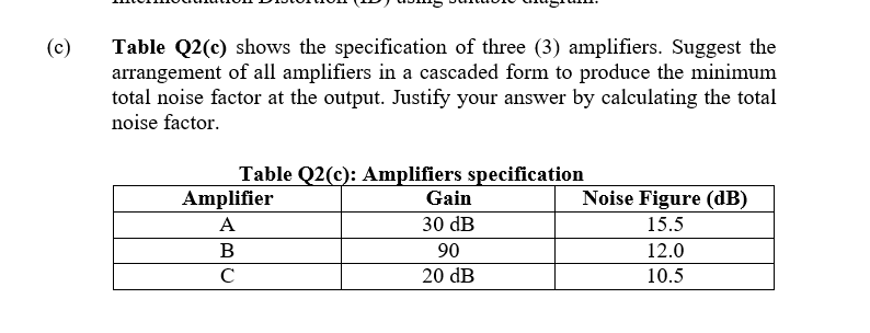
Step by step
Solved in 3 steps with 1 images
- Given in the figure is a two-stage amplifier design that employs negative feedback. Answer the following questions. Use the notation (R1 + R2 + ... + Rn) for series resistors and (R1 || R2 || ... || Rn) for parallel resistors for clarity and ease. Assume that the transistors are already biased properly in the saturation region and ro1 = ro2 → ∞. Also assume that the capacitors have infinite capacitance. 1.) Find the expression for the open loop gain Av 2.) Derive the resistance Rin which is the resistance that can be seen at the input port of the amplifierThis is a differencing of operational amplifiers problem, can you show me how is it solved? And can you also explain the steps and finish it as fast as you can? I would really appreciate it, thank you!Consider the integrating amplifier circuit in Figure 2. Using nodal analysis, derive an expression for vout for the integrating amplifier. In the circuit in Figure 2, exchange the positions of the 0.1uF capacitor and the 5k resistor. a. Use nodal analysis to generate an expression for vout. b. Using this expression, explain what function this circuit performs on an input signal.
- Outline the main features of a non-inverting operational amplifierQ.4/ Refer to the class AB power amplifier shown below:a. Determine the dc parameters VB(Q1), VB(Q2), ICQ, VCEQ(Q1), VCEQ(Q2).b. For the 5Vrms input, determine the power delivered to the load resistor.c. Determine the approximate input resistance seen by the signal source if ac=100The amplifier configuration shown in figure below is a a) common emitter b) common collector c) common base d) base follower configuration, where the is at ac ground, and the ac output voltage a) collector B) emitter C) capacitor D) base with the input. A) amplified and 180deg out of phase B) almost equal and 180degree out of phase C) almost equal and in phase D) amplified and in phase
- Slove Foperational amplifiers of your choice both FET and BJT based technologyA) From the datasheet, find the number of pins of the Op-amp IC, the open-loop gain,bandwidth, CMRR, slew rate, Voltage offset, current offset, input and output impedance,recommended supply voltages. Tabulate your outcomes with evidence from the data sheets.For both types of Op-Amps. Discus advantages and disadvantages of both.B) Mention available amplifiers that this op-amp is used for and discuss in brief itsapplications.C) Build a simple differentiator circuit, having C=1µF and R = 1kΩ for the op-amp chosen in(A), virtual using Multisim. Evaluate the voltage saturation, compare your findings with bothtypes of op-amps (FET and BJT) and analyze briefly how you concluded your result.D) Build a simple non-inverting amplifier with a gain of 10V/V circuit, using the op-ampchosen in (A) either BJT or FET, virtual using Multisim. Evaluate the slew rate, and theamplifier specification in terms of conduction angle…An amplifier is formed by cascading two operational-amplifier stages, as shown (a). (a) Replace each amplifier stage with its two-port representation. (b) Use the circuit model from part (a) to find the overall two-port representation (Av, Rin, Rout) for the complete twostageamplifier. (c) Draw the circuit of the two-port corresponding to the complete two-stage amplifier.On which criteria the power amplifiers are classified? What is the operating point of a class-A power amplifier? What is meant by efficiency? How much efficiency will be obtained in a class-A power amplifier? What are the applications of power amplifiers?
- In the circuit given in the figure, Vcc = 15 V, R1 = R2 = 10kΩ, RE = 1KΩ, RL = 0.5kΩ and transistor parameters are given as VBE = 0.7V, ßdc = ß0 = 100. a. Calculate the values of DC bias currents and voltages (IBQ, ICQ and VCEQ). b. Draw the small signal equivalent circuit of the circuit using the hybrid model of the transistor. c. Derive the input impedance expression of the circuit and calculate its value. d. Derive the AVI and AVG voltage gain expressions and calculate their values. e. Derive the current gain expression AI = I0 / Ii and calculate its value. Compare this value you have calculated with the value you will calculate using the expression Aİ = Zi AVI / RL.For the cascaded amplifier of the figure below, calculate the input impedance of the first stage, output impedance of the second stage, total voltage gain, and the output voltage if Vs= 1mV.Question 3: Please write answers to all parts of the question in the separate dot points as shown What is the circuit called? Discuss all components including voltage sources. Which components determine the closed-loop gain of the circuit? Describe the slew-rate of the op-amp. Describe the Common-Mode-Rejection ratio of the op-amp? What is the unity gain bandwidth? Describe the gain bandwidth product (GBP). Describe the GBP relationship between the break (critical) frequency and the gain? What two methods calculate the max frequency? If one produces a higher value of maximum frequency than the other, which would you use as the maximum frequency?