As shown in the figure, a rigid beam with negligible mass is pinned at one end and supported by two rods. The beam was initially horizontal before the load was applied. If P =120Kn a) Find the elongation of steel, b) elongation of aluminum and c) find the vertical movement of P. Steel E=200 GPa Aluminum E=70 GPa
Q: Q) A simply supported beam shown is loaded as shown in figurel-1. It has the cross section as shown…
A:
Q: Task 2 A force is applied in the beam shown in Figure 2. The beam is made of wood (E= 12.5 GPa, G=13…
A: Given data:E= 12.5 GPaLoad =499 N
Q: The AB rigid beam in the figure rests on AC and BD supports. The length of the AC support is LAC =…
A: Part 1) The equivalent load for a uniformly varying load w kNm acting over a beam span of L m is…
Q: A T-shape beam is a load-bearing structure. The top of the t-shape cross section serves as a flange…
A:
Q: As an engineer in a construction company, you are assigned a new job which is to design a solid,…
A: We will take aluminium 6061 -T6 alloy , Young modulus E= 69 GPa, allowable bending stress= 250 MPa,…
Q: Q) A simply supported beam shown is loaded as shown in figurel-1. It has the cross section as shown…
A:
Q: A part of a bracket seat assembly of a bus is shown in the figure below. The load on he bracket…
A:
Q: Q2) Layers of Brass, Steel and Aluminum are bonded together and formed section shown below.…
A:
Q: 60 kN/m 20 N 30 kN 10 kN/m
A:
Q: 700N M-150UNm 2m 3m For the above dlagram, given that F, - 450 N. 0-45 degrees and d-5 m calculate…
A:
Q: 2 m, as shown in the figure below. Constructed, load P=5,000 N is given perpendicular to point C.…
A: Given that, Drawing the FBD of mechanism,
Q: A cantilever beam is subjected to an inclined force (P) as shown in Figure 1, the equilibrium normal…
A: Given data :- force P = 400kN find the normal stress on the cross sectional area.
Q: Q3-B): A simply supported beam shown in Figure 3 that subjected to a uniform distributed load, if…
A: Yield stress Yield stress refers to the minimum stress at which a material will deform without…
Q: 8 em cm 1 cm 8icm 1 m 2m 1m Prob. 11.9
A:
Q: Ex: For the T beam subjected to distributed load (W), shown in figure,, the beam material can resist…
A:
Q: a) Determine the 2nd moment of area of this cross-section in Figure Q4(b)?
A: To find second moment of inertia of the cross section = ?
Q: Figure Q1 shows a cantilever beam ABCDE subjected to a uniformly distributed load, w from points B…
A: The loading diagram is Here, the UDL is extended upto point E and a upward counterbalance UDL from…
Q: H.W. 2 / Find the reactions of the simply supported beam shown in Figure below 300kN 30kNm 15kNm .B…
A: Answer: (a) The reactions at the hinge support A: (RA)x = 180 kN ; (RA)y = 165 kN. (b) The reactions…
Q: Figure Q2 (a) shows a simply supported beam ABCD under two point loadings at B and C, respectively.…
A: To find: The value of P that causes the total depth of the plastic zone to be 10 mm at the most…
Q: Question 4 a. A solid circular L shaped ABC structure is built in at one end and is point loaded at…
A:
Q: The "staircase" frame shown in the figure has a fixed support at the upper end and is free at the…
A:
Q: is made of steel material (210GPa) for the beam given below, beam cross section (dimensions mm) is…
A: 1(a) Please refer the drawing from the problem figure For uniformly distributed load, node forms at…
Q: A cantilever beam, a UPN 300 section, is subjected to its own weight and a point load at B. Find the…
A: Consider the diagram shown below for the cross-section as shown below.
Q: A beam ABCD rests on simple supports at B and C. The beam has a slight initial curvature so that end…
A:
Q: 3. A rectangular beam has an extended cantilever beam the is attached at the end of the beam. A…
A: As per given question We have to determine What is the angle of twist of the beam if the length of…
Q: A bar obtained by bonding together pieces of steel (E, = 200 GPa) and brass (E, = 103.4 GPa) has the…
A:
Q: A composite beam is fabricated by bolting two wooden boards (b = 3 in. and d = 12 in.) to the sides…
A:
Q: Consider a square-faced beam | supporting a section of a building. a) d b) c) m2 lo lo d+Ad (a)…
A: Given Data: l0=15.01 ml=14.92mm=31000 kgd=1.1 m
Q: A solid uniform brick is placed on a sheet of wood.When one end of the sheet is raised (see…
A:
Q: A cantilever composite beam is formed by bonding together brass bar (Eß = 100 GPa) and aluminium (EA…
A: Solution ,
Q: A beam supported by three identical springs at points A,B,C (see figure). Given that flexural of…
A:
Q: The figure shown below
A: The cross-sectional area of the bars is Consider the diagram shown below for the beam ACE, Taking…
Q: Q2: A simply supported beam shown in Figure (1-A) below, has the cross section shown in Figure (1-B)…
A: (a) To find: The shear force and bending moment diagram of the beam. FBD: The free body diagram of…
Q: The rigid bar of negligible weight is supported as shown in the figure. If W=60 kN, compute the…
A: Force acting in the vertical direction is vA+Ts+TB=60⋯⋯⋯(1) Moment about point A is…
Q: As in the figure, two cylindrical rods, one steel and the other brass, are combined in C. In A and…
A: Consider the free body diagram shown below for the given beam.
Q: A wire 4m long is stretched horizontally between points A and B 4m apart. A load W placed at the…
A: Given data Length of the Stretched wire = 4 mArea of cross-section of wire = 25 mm2Young's Modulus =…
Q: 2. The cross-sectional dimensions of a structural steel column, which serves as the central support…
A:
Q: 300 mm 5.5 KN 1500 mm 500 mm
A:
Q: A homogeneous, prismatic beam shown in the figure has a weight of 4.7 kN/m and is carrying a…
A:
Q: P = 36 kips |A B C 9' - 6'-
A: A beam is defined as a structural member subjected to transverse shear load during its…
Q: A (20°C) a rigid beam in placed upon the rods shown in figure: 1) Determine the magnitude of…
A: Write the given data with suitable variables. T1=20 °C∆T=100 °CAs=1000 mm2αs=12×10-6 /°CEs=200…
Q: Question Four A beam of the cross section that is shown in Figure a was supported by two rigid…
A: given data: maximum allowable tensile stress σ=50MPa own weight of beam(w)=1.5KN/mweight of beam…
Q: 2. In a laboratory test of a beam loaded by end couples, the fibers at layer AB in Figure below are…
A: In the 200 mm gauge length, we know that in a laboratory test of a beam loaded by end couplings, the…
Q: The beam shown in Figure Q3 (b) and (c) is made of steel with Young's Modulus of 200GPa and Yield…
A: Bending stress is the typical stress that an object experiences when it is subjected to a heavy load…
Q: How high should the height h of the beam cross-section be at least so that the stresses that will…
A: find reaction ant A and B. then draw S.F.D. and B.M.D. and find out maximum bending moment and…
Q: A steel wire with a diameter of d = 1/16 in. is bent around a cylindrical drum with aradius of R =…
A: The given data are:
Q: A beam weighing 50 kg is attached to a pin at C and supported by a steel cable OA with Young's…
A: 1) Free body diagram of the given beam is drawn below 2) To find Tension in the steel cable OA we…
Q: The simply supported beam is subjected to the loads as described in the figure and parameter table.…
A:
Q: The loaded frame shown in Fig. 1, is supported at A (fixed support) and B (roller support). C is an…
A: a) Reaction at support A and B The free body diagram of the right part of the hinge is here, RB is…
Please provide in clear and complete step-by-step solution in scanned handwriting and computerized output.
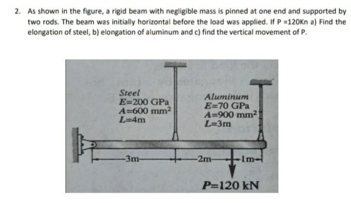
Trending now
This is a popular solution!
Step by step
Solved in 3 steps with 3 images
- A simply supported wooden I-beam with a 12-ft span supports a distributed load of intensity q = 90 lb/ft over its length (see figure part a). The beam is constructed with a web of Douglas-fir plywood and flanges of pine glued to the web, as shown in the figure part b. The plywood is 3/8 in. thick: the flanges are 2 in, × 2 in, (actual size). The modulus of elasticity for the plywood is 1,600,000 psi and for the pine is 1,200,000 psL Calculate the maximum bending stresses in the pine flanges and in the plywood web. What is q, if allowable stresses are 1600 psi in the flanges and 1200 psi in the web?A simple beam that is 18 ft long supports a uniform load of intensity q. The beam is constructed of two C8 x 11.5 sections (channel sections or C-shapes) on either side of a 4 × 8 (actual dimensions) wood beam (see the cross section shown in the figure part a). The modulus of elasticity of the steel (E; = 30,000 ksi) is 20 times that of the wood (Ew). (a) If the allowable stresses in the steel and wood are 12,000 psi and 900 psi, respectively, what is the allowable load qmax Note: Disregard the weight of the beam, and see Table F-3(a) of Appendix F for the dimensions and properties of the C-shape beam. (b) If the beam is rotated 90° to bend about its v axis (see figure part b) and uniform load q = 250 lb/ft is applied, find the maximum stresses trs and crw in the steel and wood, respectively Include the weight of the beam. (Assume weight densities of 35 lb/ft3 and 490 lb/ft3 for the wood and steel, respectively.)The cross section of a sand wie h beam consisting of aluminum alloy faces and a foam core is shown in the figure. The width b of the beam is 8.0 in, the thickness I of the faces is 0.25 in., and the height hcof the core is 5.5 in. (total height h = 6.0 in). The moduli of elasticity are 10.5 × 10⁶ psi for the aluminum faces and 12.000 psi for the foam core. A bending moment M = 40 kip-in. acts about the z axis. Determine the maximum stresses in the faces and the core using (a) the general theory for composite beams and (b) the approximate theory for sandwich beams.
- A cantilever beam has a length L = 12 ft and a rectangular cross section (b = 16 in., h = 24 in.), A linearly varying distributed load with peak intensity q0acts on the beam, (a) Find peak intensity q0if the deflection at joint B is known to be 0.18 in. Assume that modulus E = 30,000 ksi. (b) Find the location and magnitude of the maximum rotation of the beam.A steel plate (called a cover ploie) having cross-sectional dimensions 6,0 in. × 0.5 in. is welded along the full length of the bottom flange of a W 12 × 50 wide-flange beam (sec figure, which shows the beam cross section). What is the percent increase in the smaller section modulus (as compared to the wide-flange beam alone)?A beam of square cross section (a = length of each side) is bent in the plane of a diagonal (see figure). By removing a small amount of material at the top and bottom corners, as shown by the shaded triangles in the figure, you can increase the section modulus and obtain a stronger beam, even though the area of the cross section is reduced. Determine the ratio ß defining the areas that should be removed in order to obtain the strongest cross section in bending. By what percent is the section modulus increased when the areas arc removed?
- A C 200 x 17.1 channel section has an angle with equal legs attached as shown; the angle serves as a lintel beam. The combined steel section is subjected to a bending moment M having its vector directed along the z axis, as shown in the figure. The cent roi d C of the combined section is located at distances xtand ycfrom the centroid (C1) of the channel alone. Principal axes yl and yvare also shown in the figure and properties Ix1,Iy1and 0pare given. Find the orientation of the neutral axis and calculate the maximum tensile stress exand maximum compressive stress if the angle is an L 76 x 76 x 6.4 section and M = 3.5 kN - m. Use the following properties for principal axes for the combined section:/^, = 18.49 X 10⁶ nrai4,/;| = 1.602 X 106 mm4, ep= 7.448*(CW),_r£ = 10.70 mm,andvf= 24.07 mm.A seesaw weighing 3 lb/ft of length is occupied by two children, each weighing 90 lb (see figure). The center of gravity of each child is 8 ft from the fulcrum. The board is 19 ft long, 8 in. wide, and 1.5 in. thick. What is the maximum bending stress in the board?A gold-alloy microbeam attached to a silicon wafer behaves like a cantilever beam subjected to a uniform load (see figure). The beam has a length L = 27.5 m and rectangular cross section of a width b = 4.0 m and thickness t = 0.88 m. The total load on the beam is 17.2 N. If the deflection at the end of the beam is 2.46 m is what is the modulus of elasticity Egof the gold alloy? (Use the formulas of Example 9-2.)
- A reinforced concrete beam (see figure) is acted on by a positive bending moment of M = 160 kN · m. Steel reinforcement consists of 4 bars of 28 mm diameter. The modulus of elasticity for the concrete is Ec= 25 GPa while that of the steel is Es= 200 GPa. Find the maximum stresses in steel and concrete. If allowable stresses for concrete and steel are T2= 9.2 MPa and t1= 135 MPa, respectively, what is the maximum permissible positive bending moment? What is the required area of steel reinforcement, A$ if a balanced condition must be achieved? What is the allowable positive bending moment? (Recall that in a balanced design, both steel and concrete reach allowable stress values simultaneously under the design moment.)The cantilever beam AB shown in the figure has an extension BCD attached to its free end. A force P acts at the end of the extension. Find the ratio aiL so that the vertical deflection of point B will be zero. Find the ratio aiL so that the angle of rotation at point B will be zero.A bimetallic beam used in a temperature-control switch consists of strips of aluminum and copper bonded together as shown in the figure, which is a cross-sectional view. The width of the beam is LO in,, and each strip has a thickness of 1/16 in. Under the action of a bending moment M = 12 lb-in, acting about the z axis, what are the maximum stresses aaand ecin the aluminum and copper, respectively? (Assume fA, = 10,5 x l0 psi and ecu= 16,8 × 10⁶ psi,)