
Mechanics of Materials (MindTap Course List)
9th Edition
ISBN: 9781337093347
Author: Barry J. Goodno, James M. Gere
Publisher: Cengage Learning
expand_more
expand_more
format_list_bulleted
Videos
Textbook Question
Chapter 5, Problem 5.6.21P
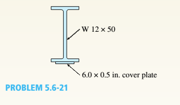
A steel plate (called a cover ploie) having cross-sectional dimensions 6,0 in. × 0.5 in. is welded along the full length of the bottom flange of a W 12 × 50 wide-flange beam (sec figure, which shows the beam cross section).
What is the percent increase in the smaller section modulus (as compared to the wide-flange beam alone)?
Expert Solution & Answer

Trending nowThis is a popular solution!

Students have asked these similar questions
Uniformly distributed load on a simple support beam with a length of 6 metersMaximum that occurs on the cross section when q is appliedIf bending stress is 337.5MPa,How many kN/m is the equal distribution load q?(However, the cross section of the beam is wide x height = 40mm x)100 mm.)
A beam is simply supported and carries the loadshown in Figure below . Specify suitable dimensionsfor the beam if it is steel and the stress is limited to18 000 psi, for the following shapes:(a) Square(b) Rectangle with height three times the width(c) Rectangle with height one-third the width(d) Solid circular section(e) American Standard beam section(f) American Standard channel with the legs down(g) Standard steel pipe
A cantilever beam AB with rectangle cross section has a longitudinal hole drilled throughout its length(see figure). The beam supports a load P=600 N. The cross section is 25 mm wide and 50 mm high, and the hole has a diameter of 10 mm.
Find the bending stresses at the top of the beam, at the top of the hole, and at the bottom of the beam.
Chapter 5 Solutions
Mechanics of Materials (MindTap Course List)
Ch. 5 - A steel wire with a diameter of d = 1/16 in. is...Ch. 5 - A copper wire having a diameter ofd = 4 mm is bent...Ch. 5 - A 4.75-in, outside diameter polyethylene pipe...Ch. 5 - A cantilever beam AB is loaded by a couple M0at...Ch. 5 - A thin strip of steel with a length of L =19 in....Ch. 5 - A bar of rectangular cross section is loaded and...Ch. 5 - A simply supported beam with a length L = 10 ft...Ch. 5 - A cantilever beam is subjected to a concentrated...Ch. 5 - A thin strip of hard copper (E = 16,000 ksi)...Ch. 5 - A steel wire (E = 200 GPa) of a diameter d = L25...
Ch. 5 - A thin, high-strength steel rule (E = 30 x 10ft...Ch. 5 - A simply supported wood beam AB with a span length...Ch. 5 - Beam ABC has simple supports at A and B and an...Ch. 5 - A simply supported beam is subjected to a in early...Ch. 5 - Each girder of the lift bridge (sec figure) is 180...Ch. 5 - A freight-car axle AS is loaded approximately as...Ch. 5 - A seesaw weighing 3 lb/ft of length is occupied by...Ch. 5 - During construction of a highway bridge, the main...Ch. 5 - The horizontal beam ABC of an oil-well pump has...Ch. 5 - A railroad tie (or sleeper) is subjected to two...Ch. 5 - A fiberglass pipe is lifted by a sling, as shown...Ch. 5 - A small dam of height h = 2.0 m is constructed of...Ch. 5 - Determine the maximum tensile stress (7, (due to...Ch. 5 - Determine the maximum bending stress emaxdue to...Ch. 5 - A simple beam A B of a span length L = 24 ft is...Ch. 5 - Determine the maximum tensile stress erand maximum...Ch. 5 - A cantilever beam A3, loaded by a uniform load and...Ch. 5 - A canti lever beam A B of a n isosceles t...Ch. 5 - A cantilever beam, a C12 x 30 section, is...Ch. 5 - A frame ABC travels horizontally with an...Ch. 5 - A beam ABC with an overhang from B to C supports a...Ch. 5 - A cantilever beam AB with a rectangular cross...Ch. 5 - A beam with a T-section is supported and loaded as...Ch. 5 - Consider the compound beam with segments AB and...Ch. 5 - A small dam of a height h = 6 ft is constructed of...Ch. 5 - A foot bridge on a hiking trail is constructed...Ch. 5 - A steel post (E=30×106) having thickness t = 1/8...Ch. 5 - Beam ABCDE has a moment release just right of...Ch. 5 - A simply supported wood beam having a span length...Ch. 5 - A simply supported beam (L = 4.5 m) must support...Ch. 5 - The cross section of a narrow-gage railway bridge...Ch. 5 - A fiberglass bracket A BCD with a solid circular...Ch. 5 - A cantilever beanie B is loaded by a uniform load...Ch. 5 - A simple beam of length L = 5 m carries a uniform...Ch. 5 - A simple beam AB is loaded as shown in the figure....Ch. 5 - A pontoon bridge (see figure) is constructed of...Ch. 5 - A floor system in a small building consists of...Ch. 5 - The wood joists supporting a plank Floor (see...Ch. 5 - A beam ABC with an overhang from B to C is...Ch. 5 - -12 A "trapeze bar" in a hospital room provides a...Ch. 5 - A two-axle carriage that is part of an over head...Ch. 5 - A cantilever beam AB with a circular cross section...Ch. 5 - A propped cantilever beam A BC (see figure) has a...Ch. 5 - A small balcony constructed of wood is supported...Ch. 5 - A beam having a cross section in the form of an un...Ch. 5 - A beam having a cross section in the form of a...Ch. 5 - Determine the ratios of the weights of four beams...Ch. 5 - Prob. 5.6.20PCh. 5 - A steel plate (called a cover ploie) having...Ch. 5 - A steel beam ABC is simply supported at A and...Ch. 5 - A retaining wall 6 ft high is constructed of...Ch. 5 - A retaining wall (Fig. a) is constructed using...Ch. 5 - A beam of square cross section (a = length of each...Ch. 5 - The cross section of a rectangular beam having a...Ch. 5 - A tapered cantilever beam A B of length L has...Ch. 5 - .2 A ligmio.irc ii supported by two vorlical beams...Ch. 5 - Prob. 5.7.3PCh. 5 - Prob. 5.7.4PCh. 5 - Prob. 5.7.5PCh. 5 - A cantilever beam AB with rectangular cross...Ch. 5 - A simple beam ABC having rectangular cross...Ch. 5 - A cantilever beam AB having rectangular cross...Ch. 5 - The shear stresses t in a rectangular beam arc...Ch. 5 - .2 Calculate the maximum shear stress tmaxand the...Ch. 5 - A simply supported wood beam is subjected to...Ch. 5 - A simply supported wood beam with overhang is...Ch. 5 - Two wood beams, each of rectangular cross section...Ch. 5 - A cantilever beam of length L = 2 m supports a...Ch. 5 - A steel beam of length L = 16 in. and...Ch. 5 - A beam of rectangular cross section (width/) and...Ch. 5 - A laminated wood beam on simple supports (figure...Ch. 5 - A laminated plastic beam of square cross section...Ch. 5 - A wood beam AB on simple supports with span length...Ch. 5 - A simply supported wood beam of rectangular cross...Ch. 5 - A square wood platform is 8 ft × 8 ft in area and...Ch. 5 - A wood beam ABC with simple supports at A and B...Ch. 5 - A wood pole with a solid circular cross section (d...Ch. 5 - A simple log bridge in a remote area consists of...Ch. 5 - A vertical pole consisting of a circular tube of...Ch. 5 - A circular pole is subjected to linearly varying...Ch. 5 - A sign for an automobile service station is...Ch. 5 - A steel pipe is subjected to a quadratic...Ch. 5 - -1 through 5.10-6 A wide-flange beam (see figure)...Ch. 5 - -1 through 5.10-6 A wide-flange beam (see figure)...Ch. 5 - -1 through 5.10-6 A wide-flange beam (see figure)...Ch. 5 - -1 through 5.10-6 A wide-flange beam (see figure)...Ch. 5 - -1 through 5.10-6 A wide-flange beam (see figure)...Ch. 5 - -1 through 5.10-6 A wide-flange beam (see figure)...Ch. 5 - A cantilever beam AB of length L = 6.5 ft supports...Ch. 5 - A bridge girder A B on a simple span of length L =...Ch. 5 - A simple beam with an overhang supports a uniform...Ch. 5 - A hollow steel box beam has the rectangular cross...Ch. 5 - A hollow aluminum box beam has the square cross...Ch. 5 - The T-beam shown in the figure has cross-sectional...Ch. 5 - Calculate the maximum shear stress tmax. in the...Ch. 5 - A prefabricated wood I-beam serving as a floor...Ch. 5 - A welded steel gird crhaving the erass section...Ch. 5 - A welded steel girder having the cross section...Ch. 5 - A wood box beam is constructed of two 260 mm × 50...Ch. 5 - A box beam is constructed of four wood boards as...Ch. 5 - Two wood box beams (beams A and B) have the same...Ch. 5 - A hollow wood beam with plywood webs has the...Ch. 5 - A beam of a T cross section is formed by nailing...Ch. 5 - The T-beam shown in the figure is fabricated by...Ch. 5 - A steel beam is built up from a W 410 × 85 wide...Ch. 5 - The three beams shown have approximately the same...Ch. 5 - Two W 310 × 74 Steel wide-flange beams are bolted...Ch. 5 - A pole is fixed at the base and is subjected to a...Ch. 5 - A solid circular pole is subjected to linearly...Ch. 5 - While drilling a hole with a brace and bit, you...Ch. 5 - An aluminum pole for a street light weighs 4600 N...Ch. 5 - A curved bar ABC having a circular axis (radius r...Ch. 5 - A rigid Trame ABC is formed by welding two steel...Ch. 5 - A palm tree weighing 1000 lb is inclined at an...Ch. 5 - A vertical pole of aluminum is fixed at the base...Ch. 5 - Because of foundation settlement, a circular tower...Ch. 5 - A steel bracket of solid circular cross section is...Ch. 5 - A cylindrical brick chimney of height H weighs w =...Ch. 5 - A flying but tress transmit s a load P = 25 kN,...Ch. 5 - A plain concrete wall (i.e., a wall with no steel...Ch. 5 - A circular post, a rectangular post, and a post of...Ch. 5 - Two cables, each carrying a tensile force P = 1200...Ch. 5 - Prob. 5.12.16PCh. 5 - A short column constructed of a W 12 × 35...Ch. 5 - A short column with a wide-flange shape is...Ch. 5 - A tension member constructed of an L inch angle...Ch. 5 - A short length of a C 200 × 17.1 channel is...Ch. 5 - The beams shown in the figure are subjected to...Ch. 5 - The beams shown in the figure are subjected to...Ch. 5 - A rectangular beam with semicircular notches, as...Ch. 5 - A rectangular beam with semicircular notches, as...Ch. 5 - A rectangular beam with notches and a hole (see...
Knowledge Booster


Learn more about
Need a deep-dive on the concept behind this application? Look no further. Learn more about this topic, mechanical-engineering and related others by exploring similar questions and additional content below.Similar questions
- Two wood beams, each of rectangular cross section (3.0 in. x 4.0 in., actual dimensions), are glued together to form a solid beam with dimensions 6.0 in. x 4.0 in. (sec figure). The beam is simply supported with a span of S ft. What is the maximum moment Mmaxthat may be applied at the left support if the allowable shear stress in the glued joint is 200 psi? (Include the effects of the beams own weight, assuming that the wood weighs 35 lb/ft3.) Repeat part (a) if Mmaxis based on allowable bending stress of 2500 psi.arrow_forwardA pontoon bridge (see figure) is constructed of two longitudinal wood beams, known as bulks, that span between adjacent pontoons and support the transverse floor beams, which arc called chesses. For purposes of design, assume that a uniform floor load of 7.5 kPa acts over the chesses. (This load includes an allowance for the weights of the chesses and balks.) Also, assume that the chesses are 2.5 m long and that the balks are simply supported with a span of 3.0 m. The allowable bending stress in the wood is 15 MPa. If the balks have a square cross section, what is their minimum required width b^l Repeat part (a) if the balk width is 1.5 b and the balk depth is b; compare the cross-sectional areas of the two designs.arrow_forwardTwo flat beams AB and CD, lying in horizontal planes, cross at right angles and jointly support a vertical load P at their midpoints (see figure). Before the load P is applied, the beams just touch each other. Both beams are made of the same material and have the same widths. Also, the ends of both beams are simply supported. The lengths of beams AB and CD are LABand LCD, respectively. What should be the ratio tABltCDof the thicknesses of the beams if all four reactions arc to be the same?arrow_forward
- A simply supported wooden I-beam with a 12-ft span supports a distributed load of intensity q = 90 lb/ft over its length (see figure part a). The beam is constructed with a web of Douglas-fir plywood and flanges of pine glued to the web, as shown in the figure part b. The plywood is 3/8 in. thick: the flanges are 2 in, × 2 in, (actual size). The modulus of elasticity for the plywood is 1,600,000 psi and for the pine is 1,200,000 psL Calculate the maximum bending stresses in the pine flanges and in the plywood web. What is q, if allowable stresses are 1600 psi in the flanges and 1200 psi in the web?arrow_forwardA simple beam that is 18 ft long supports a uniform load of intensity q. The beam is constructed of two C8 x 11.5 sections (channel sections or C-shapes) on either side of a 4 × 8 (actual dimensions) wood beam (see the cross section shown in the figure part a). The modulus of elasticity of the steel (E; = 30,000 ksi) is 20 times that of the wood (Ew). (a) If the allowable stresses in the steel and wood are 12,000 psi and 900 psi, respectively, what is the allowable load qmax Note: Disregard the weight of the beam, and see Table F-3(a) of Appendix F for the dimensions and properties of the C-shape beam. (b) If the beam is rotated 90° to bend about its v axis (see figure part b) and uniform load q = 250 lb/ft is applied, find the maximum stresses trs and crw in the steel and wood, respectively Include the weight of the beam. (Assume weight densities of 35 lb/ft3 and 490 lb/ft3 for the wood and steel, respectively.)arrow_forwardA bimetallic beam used in a temperature-control switch consists of strips of aluminum and copper bonded together as shown in the figure, which is a cross-sectional view. The width of the beam is LO in,, and each strip has a thickness of 1/16 in. Under the action of a bending moment M = 12 lb-in, acting about the z axis, what are the maximum stresses aaand ecin the aluminum and copper, respectively? (Assume fA, = 10,5 x l0 psi and ecu= 16,8 × 10⁶ psi,)arrow_forward
- A square wood platform is 8 ft × 8 ft in area and rests on masonry walls (see figure). The deck of the platform is constructed of 2-in. nominal thickness tongue-and-groove planks (actual thickness 1.5 in.; sec Appendix CL) supported on two S-ft long beams. The beams have 4 in. × (i in. nominal dimensions (actual dimensions 3.5 in. × 5.5 in.). The planks arc designed to support a uniformly distributed load n ( lb/ft" i acting over the entire top surface of the platform. I be allowable bending stress for the planks is 2400 psi and the allowable shear stress is 100 psi. W ben analyzing the planks, disregard their weights and assume that their reactions are uniformly distributed over the top surfaces of the supporting beams. (a) Determine the allowable platform load Mr. (lb/ft2) based upon the bending stress in the planks. (b) Determine the allowable platform load if-. (lb/ft-) based upon the shear stress in the planks. (c) Which of the preceding values becomes the allowable load alolow on the platform? Hints: Use care in constructing the loading diagram for the planks, noting especially that the reactions are distributed loads instead of concentrated loads. Also, note that the maximum shear forces occur at the inside faces of the supporting beams.arrow_forwardEach girder of the lift bridge (sec figure) is 180 ft long and simply supported at the ends. The design load for each girder is a uniform load of intensity 1,6 kips/ft. The girders are fabricated by welding three steel plates to form an I-shaped cross section (see figure) having section modulus S = 3600 in3. What is the maximum bending stress rmaxin a girder due to the uniform load?arrow_forwardCalculate the maximum normal stress in the cross section of the beam shown in the figure, whose radius is 9 cm.arrow_forward
- The figure shows a reinforced wooden beam with an aluminum channel section as seen in the figure. The beam has a cross section with dimensions of 6 in. by 10 in., and the channel has a uniform thickness of 0.25 in. If the allowable stresses in wood and aluminum are 1160 psi and 5500 psi, respectively, and if their moduli of elasticity have a ratio of 1 to 6, what is the maximum allowable bending moment for the beam?arrow_forwardA thin strip of hard copper (E = 16,000 ksi) having length L= 90 in, and thickness t=3/32 in. is bent into a circle held with the ends just touching a) Calculate the maximum bending stress in the strip b) By what percent does the stress increase or decrease if the thickness of the strip is increased by 1/32 in?arrow_forwardA brass strip, 50 mm x 12 mm in section, is riveted to a steel strip, Figure (22) 65 mm x 10 mm in section, to form a compound beam of total depth 22 mm, the brass strip being on top and the beam section being symmetrical about the vertical axis. The beam is simply supported on a span of 1.3 m and carries a load of 2 kN at mid-span. (a) Determine the maximum stresses in each of the materials owing to bending. (b) Make a diagram showing the distribution of bending stress over the depth of the beam. Take E for steel = 200 GN/m² and E for brass = 100 GN/m². Ans.( 0) = 130 MN/m²; 0, = 162.9 MN/m²]arrow_forward
arrow_back_ios
SEE MORE QUESTIONS
arrow_forward_ios
Recommended textbooks for you
 Mechanics of Materials (MindTap Course List)Mechanical EngineeringISBN:9781337093347Author:Barry J. Goodno, James M. GerePublisher:Cengage Learning
Mechanics of Materials (MindTap Course List)
Mechanical Engineering
ISBN:9781337093347
Author:Barry J. Goodno, James M. Gere
Publisher:Cengage Learning
Mechanics of Materials Lecture: Beam Design; Author: UWMC Engineering;https://www.youtube.com/watch?v=-wVs5pvQPm4;License: Standard Youtube License