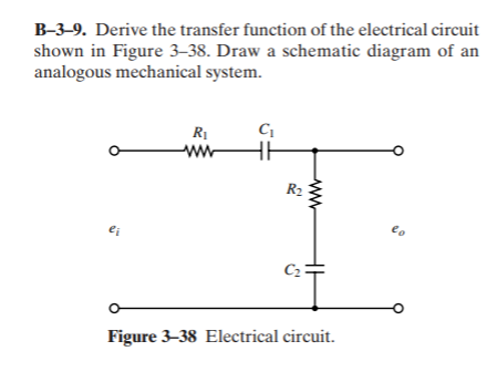
B-3–9. Derive the transfer function of the electrical circuit shown in Figure 3–38. Draw a schematic diagram of an analogous mechanical system. RI R2 Figure 3–38 Electrical circuit. ww
B-3–9. Derive the transfer function of the electrical circuit shown in Figure 3–38. Draw a schematic diagram of an analogous mechanical system. RI R2 Figure 3–38 Electrical circuit. ww

Chapter32: Two-speed, One-winding (consequent Pole) Motor Controllers
Section: Chapter Questions
Problem 6SQ: Describe the operation of Figure 325 (B) by adding jumper wire A to the original circuit.

Related questions

Question
Transcribed Image Text:shown in Figure 3–38. Draw a schematic diagram of an
analogous mechanical system.
B-3–9. Derive the transfer function of the electrical circuit
RỊ
ww
R2
eo
ei
Figure 3–38 Electrical circuit.
ww
Expert Solution
This question has been solved!
Explore an expertly crafted, step-by-step solution for a thorough understanding of key concepts.

This is a popular solution!

Trending now
This is a popular solution!

Step by step
Solved in 5 steps with 6 images

Knowledge Booster


Learn more about
Need a deep-dive on the concept behind this application? Look no further. Learn more about this topic, electrical-engineering and related others by exploring similar questions and additional content below.Recommended textbooks for you

Delmar's Standard Textbook Of Electricity
Electrical Engineering
ISBN:
9781337900348
Author:
Stephen L. Herman
Publisher:
Cengage Learning

EBK ELECTRICAL WIRING RESIDENTIAL
Electrical Engineering
ISBN:
9781337516549
Author:
Simmons
Publisher:
CENGAGE LEARNING - CONSIGNMENT
Delmar's Standard Textbook Of Electricity
Electrical Engineering
ISBN:
9781337900348
Author:
Stephen L. Herman
Publisher:
Cengage Learning
EBK ELECTRICAL WIRING RESIDENTIAL
Electrical Engineering
ISBN:
9781337516549
Author:
Simmons
Publisher:
CENGAGE LEARNING - CONSIGNMENT

Power System Analysis and Design (MindTap Course …
Electrical Engineering
ISBN:
9781305632134
Author:
J. Duncan Glover, Thomas Overbye, Mulukutla S. Sarma
Publisher:
Cengage Learning