A beam shown in Figure 6.20 is made of T beam, determine maximum bending stress in tension and compression develop due to various type of loading.
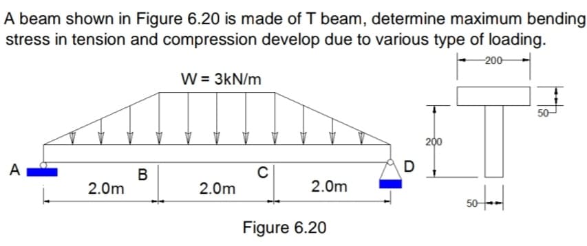
 -200 W = 3kN/m 50 200 A D B 2.0m 2.0m 2.0m 50- Figure 6.20
Q: A simply supported beam with span of 8 m is subjected to a counterclockwise moment at the left…
A: Given Data The length of the beam is:L=8m The yield strength of the steel beam is:Fy=248 MPa The…
Q: A beam of circular section is subjected to a load of 4kN. If the diameter of the circular section is…
A: Given data: F=4 kNd=0.1 m Need to determine the maximum shear stress.
Q: On a structural steel I profile beam a distributed load and M moment is applied as shown in the…
A: Given data On a structural steel I profile beam a distributed load and M moment is applied as shown…
Q: Q1) Find the values of the maximum tensile and compressive bending stresses for the simply supported…
A: As per bartleby guidelines we are allowed to solve only 1st question if multiple questions are…
Q: A wood beam carries the loading shown in the figure. Calculate the magnitude of the bending stress…
A:
Q: 1. Simulate for the maximum shear stress and strain on a beam as shown in figure below. 75 N 125 N-m…
A:
Q: For the wood beam shown in Figure A, assume L = 1.3 m and P = 11 kN. The beam cross section shown in…
A: Here we need to apply the concepts pf SFD and Bending of beams...
Q: A beam has a bending moment of 2.5 kN-m applied to a section with a hollow circular cross-section of…
A: Since we only answer up to 3 sub-parts, we’ll answer the first 3. Please resubmit the question and…
Q: The beam W24x104 beam is constructed of A-36 steel. AC has a cross-sectional area of 1 square inch…
A: For W24×104,I=3100 in4For A-36 steel,E=210 GPa=3.046×10⁷ lb/in2, The deflection due to the UDL of…
Q: 1. The shearing stress developed at the neutral axis of a beam with circular cross section is a)…
A: Stress: Stress is a ratio of force per unit area. It is denoted by the σ and unit is newton per…
Q: 25 kips 20 in.- Figure 1 10 in. 25 kips 20 in. B 7.25 in. Sin.- b 1.5 in. 1.5 in.
A:
Q: Let's consider a fixed supported beam subjected to a triangular distributed load as shown in the…
A: Let us mention reactions developed at fixed end in the figure: We can replace given UDL of w =…
Q: Lets consider a cantilevered beam subjected to a uniform trectangular) load with intensity 4 kN/m.…
A: Shear force diagram represents shear force at every section of the beam..Shear force at any…
Q: A beam has a bending moment of 4 kN-m applied to a section with a hollow circular cross-section of…
A: Given data: The maximum bending moment is M = 4 kN-m. The external diameter of the beam is D = 3.7…
Q: Figure 1. 40 kN 30 kN/m 20 KN B K A -2m+ K 2m Re RA Figure 1. 85 mmm 68 mm Section K-K
A:
Q: For the wood beam shown in Figure A, assume L = 1.5 mand P = 15 kN. The beam cross section shown in…
A:
Q: Q2: For the beam shown in Figure (2), determine transverse shear stresses at points E, F and G on…
A: Find the transverse shear stress .
Q: A circular beam carries a concentrated and a distributed load as shown in the figure. Determine the…
A: An overhanging beam is one in which the terminal portion of the beam extends beyond the support.…
Q: Problem 1) Cross section of a beam was shown in the below figure. Suppose that this beam is…
A: Given: The bending moment, M = 10 kN.m
Q: 3. A rectangular beam has an extended cantilever beam the is attached at the end of the beam. A…
A: As per given question We have to determine What is the angle of twist of the beam if the length of…
Q: rectangular bar having width twice the depth is used as a beam. The beam is made of mild steel…
A:
Q: b) A uniform I-section cantilever beam, built-in at one end and roller supported at the other, with…
A:
Q: The bending moment Mx affects the cross section of the beam given in Figure 4. Beam cross section…
A: I have given the answer in the steps below, Please consider UPVOTING this answer, it boosts my…
Q: Cross section of a beam is shown in Figure 3. If a shear force V=100 kN is applied to the beam, find…
A:
Q: Q1 Calculate the bending stresses at top and bottom fibers of a simply supported beam and loaded as…
A:
Q: A bar obtained by bonding together pieces of steel (E, = 200 GPa) and brass (E, = 103.4 GPa) has the…
A:
Q: on 5 Let's consider a fixed supported beam subjected to a triangular distributed load as shown in…
A:
Q: Consider the simple beam in Figure 7 with two concentrated loads, where AB-BC=CD=4m: 6kN 12kN 12m…
A:
Q: For the simply supported beam in figure, the shear force at midspan equals: 80 kN 80 kN 2 4 m Select…
A: Given, External force = 80 kN
Q: A beam has a bending moment of 3 kN-m applied to a section with a hollow circular cross-section of…
A: We are suppose to solve only 3 subparts. Please post other parts as separate question.
Q: Example 1 The bar is subjected to a moment of M = 17.5 N.m. If r = 5 mm, determine the maximum…
A: Introduction: Bending stress is the typical stress that an item experiences when subjected to a…
Q: 9 A rectangular cross section beam of width 0.25 m and depth 0.4 m is subjected to a bending moment…
A: Calculated distance from the top surface where normal stress will be zero.
Q: A wood beam carries the loading shown in the figure. calculate the maximum bending stress (in Pa) if…
A:
Q: A built-in cantilever beam with a hollow rectangular cross-section is subjected to a uniformly…
A: The variation of shear force for a cantilever subjected to UDL is to be identified. Shear force…
Q: The dimensions of a rectangular beam are limited to b = 300 mm and effective depth, d = 700 mm.…
A: according to given details
Q: Span, shear force (T) and bending of the beam whose loading condition is given in Figure 4 Draw…
A: The question shows an overhanging simply supporting beam. To draw the bending moment moment diagram,…
Q: The iron beam with E=120 GPa as shown in Figure 2, is subjected to a moment of 600 N.m. 25 mm 150 mm…
A:
Q: 1. Draw shear force and bending moment diagrams for the beam shown in figure. 30kN 2m B 10KN/m C 10m
A: First calculate the reactions at the supports,
Q: Draw free body diagram without writing shear and moment equation of beam shown in Figure 2.19. Give…
A:
Q: Draw shear force and bending moment diagrams P= 1000 N --w = 250 N/cm B 5 cm 20 cm Figure 1.2 (not…
A: Sign convention For shear force 1) RUN (right upward negative) 2) RDP ( Right Downward Positive) 3)…
Q: A beam has a bending moment of 3 kN-m applied to a section with a hollow circular cross-section of…
A: We are suppose to solve only 3 subparts. Please post other parts as a separate question.
Q: Draw shear force and bending moment diagram of the beam loaded as shown in the figure. 20 kN 12 kN…
A:
Q: The bending moment acting on the triangular cross section of a beam is M = 36 kN.m (concave upward).…
A: Data given -
Q: The iron beam with E=120 GPa as shown in Figure 2, is subjected to a moment of 600 N.m. 25 mm 150 mm…
A:
Q: ter of the beam must be at least how many mm so that the amount of collapse that will occur at point…
A: We will find out the deflection at B due to point load and moment and equate it with permissible…
Q: An extruded polymer beam is subjected to a bending moment M. The length of the beam is L = 620 mm.…
A: Given data L = 620 mm b1 = 39 mmd1 = 82 mmb2 = 23 mmd2 = 23 mma = 8 mmAllowable tensile bending…
Q: A simply supported steel beam is subjected to a uniformly distributed load as shown in Figure E5.2.…
A:
Q: Calculate the vertical shear stress (N / cm2) at point A in the critical section of the beam below…
A: Please refer to the detailed attached solution:
Q: 2a) a uniformly distributed load beam has a cross-sectional area as shown in Figure 2(a) i.…
A:
Step by step
Solved in 3 steps with 6 images
- A weight W = 4000 lb falls through a height h = 0.5 in, onto the midpoint of a simple beam of length L = 10 ft (see figure). Assuming that the allowable bending stress in the beam is = 18,000 psi and E = 30 x 10* psi, select the lightest wide-flange beam listed in Table F-l(a) in Appendix F that will be satisfactory.A beam of wide-flange shape, W 8 x 28, has the cross section shown in the figure. The dimensions are b = 6.54 in., h = 8.06 in., fw = 0.285 in., and tf = 0.465 in.. The loads on the beam produce a shear force V = 7.5 kips at the cross section under consideration. Use center line dimensions to calculate the maximum shear stress raiaxin the web of the beam. Use the more exact analysis of Section 5,10 in Chapter 5 to calculate the maximum shear stress in the web of the beam and compare it with the stress obtained in part .A frame ABCD is constructed of steel wide-flange members (W8 x 21; E = 30 x ID6 psi) and subjected to triangularly distributed loads of maximum intensity q0acting along the vertical members (see figure). The distance between supports is L = 20 ft and the height of the frame is h = 4 ft. The members are rigidly connected at B and C. Calculate the intensity of load q0 required to produce a maximum bending moment of 80 kip-in. in the horizontal member BC. If the load q0 is reduced to one-half of the value calculated in part (a), what is the maximum bending moment in member BC? What is the ratio of this moment to the moment of 80 kip-in. in part (a)?
- The cross section of a sand wie h beam consisting of aluminum alloy faces and a foam core is shown in the figure. The width b of the beam is 8.0 in, the thickness I of the faces is 0.25 in., and the height hcof the core is 5.5 in. (total height h = 6.0 in). The moduli of elasticity are 10.5 × 10⁶ psi for the aluminum faces and 12.000 psi for the foam core. A bending moment M = 40 kip-in. acts about the z axis. Determine the maximum stresses in the faces and the core using (a) the general theory for composite beams and (b) the approximate theory for sandwich beams.A cantilever beam AB having rectangular cross sections with varying width bxand varying height hxis subjected to a uniform load of intensity q (sec figure). If the width varies linearly with x according to the equation hx= bBxiL^ how should the height hxvary as a function of v in order to have a fully stressed beam? (Express hxin terms of the height hBat the fixed end of the beam.)The hollow box beam shown in the figure is subjected to a bending moment M of such magnitude that the flanges yield but the webs remain linearly elastic. (a) Calculate the magnitude of the moment M if the dimensions of the cross section are A = 15 in., A] = 12.75 in., h = 9 in., and ey =7.5 in. Also, the yield stress is eY = 33 ksi. (b) What percent of the moment M is produced by the elastic core?
- A cantilever beam of a length L = 2.5 ft has a rectangular cross section {b = 4in,, h = Sin,) and modulus E = 10,000 ksi. The beam is subjected to a linearly varying distributed load with a peak intensity qQ= 900 lb/ft. Use the method of superposition and Cases 1 and 9 in Table H-l to calculate the deflection and rotation at B.A W 12 x 50 steel wide-flange beam and a segment of a 4-inch thick concrete slab (see figure) jointly resist a positive bending moment of 95 kip-ft. The beam and slab are joined by shear connectors that are welded to the steel beam. (These connectors resist the horizontal shear at the contact surface.) The moduli of elasticity of the steel and the concrete are in the ratio 12 to 1. Determine the maximum stresses r1 and xtin the steel and concrete, respectively. Note: See Table F-l(a) of Appendix F for the dimensions and properties of the steel beam.A simple beam AB of length L and height h (see figure) is heated in such a manner that the temperature difference 7= T{between the bottom and top of the beam is proportional to the distance from support A: that is, assume the temperature difference varies linearly along the beam: T2- Tt= Tax in which 7"0 is a constant having units of temperature (degrees) per unit distance. Determine the maximum deflection SW9Xof the beam, Repeat for a quadratic temperature variation along the beam, so T2+T1= Tax
- .2 A ligmio.irc ii supported by two vorlical beams consistins: of thin-walled, tapered circular lubes (see ligure part at. for purposes of this analysis, each beam may be represented as a cantilever AB of length L = 8.0 m subjected to a lateral load P = 2.4 kN at the free end. The tubes have a constant thickness ; = 10.0 mm and average diameters dA = 90 mm and dB = 270 mm at ends A and B, re s pec lively. Because the thickness is small compared to the diameters, the moment of inerlia at any cross section may be obtained from the formula / = jrrf3;/8 (see Case 22, Appendix E); therefore, the section modulus mav be obtained from the formula S = trdhlA. (a) At what dislance A from the free end docs the maximum bending stress occur? What is the magnitude trllul of the maximum bending stress? What is the ratio of the maximum stress to the largest stress (b) Repeat part (a) if concentrated load P is applied upward at A and downward uniform load q {-x) = 2PIL is applied over the entire beam as shown in the figure part b What is the ratio of the maximum stress to the stress at the location of maximum moment?A propped cantilever beam, fixed at the left-hand end A and simply supported at the right-hand end B, is subjected to a temperature differentia] with temperature T1on its upper surface and T2on its lower surface (see figure).A wide-flange member (W200 × 22.5) is compressed by axial loads that have a resultant P acting at the point shown in the figure. The member has modulus of elasticity E = 200 GPa and pinned conditions at the ends. Lateral supports prevent any bending about the weak axis of the cross section. If the length of the member is 6.2 m and the deflection is limited to 6.5 mm. what is the maximum allowable load Pallow.