6. A cantilever beam with cross section shown in Figure 4 and span of 3.6 concentrated load (P) at the free end. If the maximum allowable shearing MPa what is the maximum value of the load P can be applied. 200 mm
6. A cantilever beam with cross section shown in Figure 4 and span of 3.6 concentrated load (P) at the free end. If the maximum allowable shearing MPa what is the maximum value of the load P can be applied. 200 mm

Mechanics of Materials (MindTap Course List)
9th Edition
ISBN:9781337093347
Author:Barry J. Goodno, James M. Gere
Publisher:Barry J. Goodno, James M. Gere
Chapter5: Stresses In Beams (basic Topics)
Section: Chapter Questions
Problem 5.11.7P: A hollow wood beam with plywood webs has the cross-s cet ion a I dimensions shown in the figure. The...

Related questions
Question
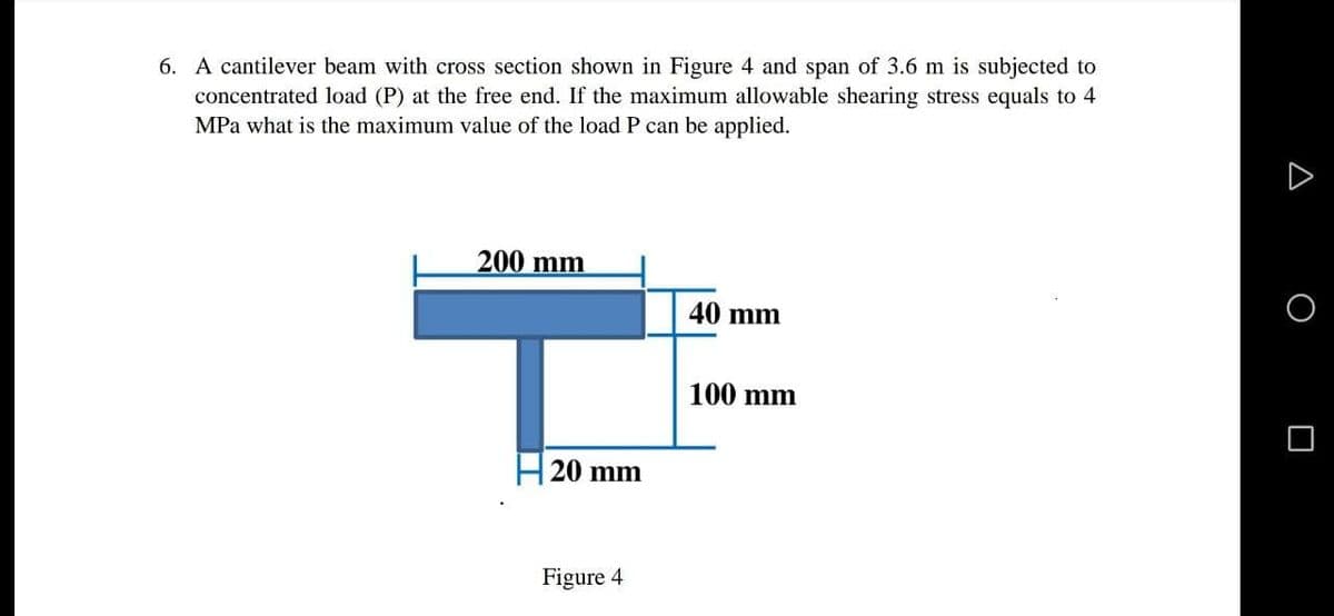
Transcribed Image Text:6. A cantilever beam with cross section shown in Figure 4 and span of 3.6 m is subjected to
concentrated load (P) at the free end. If the maximum allowable shearing stress equals to 4
MPa what is the maximum value of the load P can be applied.
200 mm
40 mm
100 mm
20 mm
Figure 4
Expert Solution
This question has been solved!
Explore an expertly crafted, step-by-step solution for a thorough understanding of key concepts.

Step by step
Solved in 2 steps with 1 images

Knowledge Booster


Learn more about
Need a deep-dive on the concept behind this application? Look no further. Learn more about this topic, mechanical-engineering and related others by exploring similar questions and additional content below.Recommended textbooks for you
Mechanics of Materials (MindTap Course List)
Mechanical Engineering
ISBN:
9781337093347
Author:
Barry J. Goodno, James M. Gere
Publisher:
Cengage Learning
Mechanics of Materials (MindTap Course List)
Mechanical Engineering
ISBN:
9781337093347
Author:
Barry J. Goodno, James M. Gere
Publisher:
Cengage Learning