B2 A tube of 50 mm outside diameter and 2 mm thickness is attached at the ends by means of rigid flanges to a solid shaft of 25 mm diameter as shown in Figure B2. A torque of T is applied at the ends of the assembly as shown in the diagram. 25mm 2mm O Ho 500mm (All dimensions in mm. Diagram not drawn to scale.) Figure B2 a) If both the tube and the shaft are made of the same linearly elastic material, what is the part (percentage) of the applied torque T carried by the tube? (hint: consider equal angle of rotation of the tube and the shaft) b) If the assembly is made of aluminium, what is the maximum torque T that can be applied to the assembly such that the shearing stress in the tube would not exceed 100 MPa? A 25mm 50mm
B2 A tube of 50 mm outside diameter and 2 mm thickness is attached at the ends by means of rigid flanges to a solid shaft of 25 mm diameter as shown in Figure B2. A torque of T is applied at the ends of the assembly as shown in the diagram. 25mm 2mm O Ho 500mm (All dimensions in mm. Diagram not drawn to scale.) Figure B2 a) If both the tube and the shaft are made of the same linearly elastic material, what is the part (percentage) of the applied torque T carried by the tube? (hint: consider equal angle of rotation of the tube and the shaft) b) If the assembly is made of aluminium, what is the maximum torque T that can be applied to the assembly such that the shearing stress in the tube would not exceed 100 MPa? A 25mm 50mm

Mechanics of Materials (MindTap Course List)
9th Edition
ISBN:9781337093347
Author:Barry J. Goodno, James M. Gere
Publisher:Barry J. Goodno, James M. Gere
Chapter3: Torsion
Section: Chapter Questions
Problem 3.4.5P: A hollow tube ABCDE constructed of monel metal is subjected to five torques acting in the directions...

Related questions
Question
Can part b) be answered please?
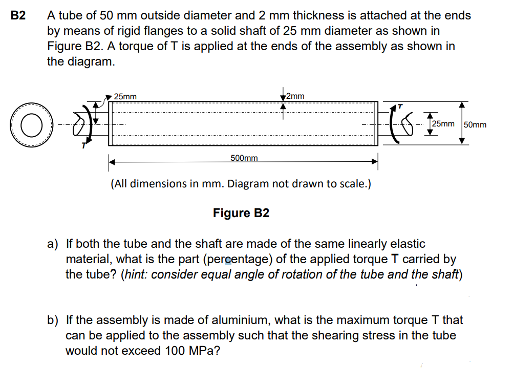
Transcribed Image Text:B2
A tube of 50 mm outside diameter and 2 mm thickness is attached at the ends
by means of rigid flanges to a solid shaft of 25 mm diameter as shown in
Figure B2. A torque of T is applied at the ends of the assembly as shown in
the diagram.
25mm
2mm
to-
25mm 50mm
500mm
(All dimensions in mm. Diagram not drawn to scale.)
Figure B2
a) If both the tube and the shaft are made of the same linearly elastic
material, what is the part (percentage) of the applied torque T carried by
the tube? (hint: consider equal angle of rotation of the tube and the shaft)
b) If the assembly is made of aluminium, what is the maximum torque T that
can be applied to the assembly such that the shearing stress in the tube
would not exceed 100 MPa?
Expert Solution
This question has been solved!
Explore an expertly crafted, step-by-step solution for a thorough understanding of key concepts.

This is a popular solution!

Trending now
This is a popular solution!

Step by step
Solved in 2 steps with 2 images

Knowledge Booster


Learn more about
Need a deep-dive on the concept behind this application? Look no further. Learn more about this topic, mechanical-engineering and related others by exploring similar questions and additional content below.Recommended textbooks for you
Mechanics of Materials (MindTap Course List)
Mechanical Engineering
ISBN:
9781337093347
Author:
Barry J. Goodno, James M. Gere
Publisher:
Cengage Learning
Mechanics of Materials (MindTap Course List)
Mechanical Engineering
ISBN:
9781337093347
Author:
Barry J. Goodno, James M. Gere
Publisher:
Cengage Learning