
Concept explainers
Videos
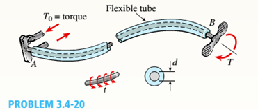
A magnesium-alloy wire of diameter d = 4mm and length L rotates inside a flexible tube in order to open or close a switch from a remote location (see figure). A torque Tis applied manually (either clockwise or counterclockwise) at end 5, thus twisting the wire inside the tube. At the other end A, the rotation of the wire operates a handle that opens or closes the switch.
A torque T0 = 0.2 N · m is required to operate the switch. The torsional stiffness of the tube, combined with friction between the tube and the wire, induces a distributed torque of constant intensity t = 0.04N − m/m (torque per unit distance) acting along the entire length of the wire.
(a)
If the allowable shear stress in the wire is T allow = 30 MPa, what is the longest permissible length Lmaxof the wire?
Want to see the full answer?
Check out a sample textbook solution
Chapter 3 Solutions
Mechanics of Materials (MindTap Course List)


- A tubular bar with outside diameterd2= 4.0 in, is twisted by torques T = 70,0 kip-in. (see figure). Under the action of these torques, the maximum tensile stress in the bar is found to be 6400 psi. Determine the inside diameter rtf of the bar. If the bar has length L = 48.0 in. and is made of aluminum with shear modulus G = 4,0 × 10⁶ psi, what is the angle of twist d (in degrees) between the ends of the bar? (c) Determine the maximum shear strain y (in radians)?arrow_forwardA hollow steel shaft used in a construction auger has an outer diameter d2= 6.0 in. and inner diameter d1= 4.5 in. (see figure). The steel has a shear modulus of elasticity G = 11.0 × 10⁶ psi. For an applied torque of 150 kip-in., determine the following quantities: shear stress at the outer surface of the shaft, shear stress at the inner surface, and rate of twist (degrees per unit of length). Also, draw a diagram showing how the shear stresses vary in magnitude along a radial line in the cross section.arrow_forwardA solid steel bar of diameter d1= 1.50 in. is enclosed by a steel tube of outer diameter d3= 2.25 in, and inner diameter d2= 1,75 in. (see figure). Both bar and tube arc held rigidly by a support at end A and joined securely to a rigid plate at end B. The composite bar, which has length L = 30.0 in., is twisted by a torque T = 5000 lb-in, acting on the end plate. Determine the maximum shear stresses r, and r2in the bar and tube, respectively. Determine the angle of rotation 0 (in degrees) of the end plate, assuming that the shear modulus of the steel is G = 116 × 106 psi. Determine the torsional stiffness kTof the composite bar.arrow_forward
- A uniformly tapered lube AB of circular cross section and length L is shown in the figure. The average diameters at the ends are dAand d£= 2d t. Assume E is constant. Find the elongation S of the tube when it is subjected to loads P acting at the ends. Use the following numerical data:^ = 35 mm, L = WO mm, E = 2.1 GPa. and P = 25 tN. Consider the following cases. (a) A hole of constant diameter dAis drilled from B toward A to form a hollow section of length x - U2. (b) A hole of variable diameter a\.x) is drilled, from B toward A to form a hollow section of length x = L/2 and constant thickness t = dA/20.arrow_forwardA hollow circular tube T of a length L = 15 in. is uniformly compressed by a force P acting through a rigid plate (see figure). The outside and inside diameters of the tube are 3.0 and 2.75 in., respectively. A concentric solid circular bar B of 1.5 in. diameter is mounted inside the lube. When no load is present, there is a clearance c = 0.0I0 in. between the bar B and the rigid plate. Both bar and tube are made of steel having an c[autoplastic stress-strain diagram with E = 29 X LO3 ksi and err= 36 ksi. (a) Determine the yield load Pt- and the corresponding shortening 3yof the lube. (b) Determine the plastic load Ppand the corresponding shortening Spof the tube. (c) Construct a load-displacement diagram showing the load Pas ordinate and the shortening 5 of the tube as abscissa. Hint: The load-displacement diagram is not a single straight line in the region 0 ^ P ^ Prarrow_forwardA vertical pole of solid, circular cross section is twisted by horizontal forces P = 5kN acting at the ends of a rigid horizontal arm AB (see figure part a). The distance from the outside of the pole to the line of action of each force is c = 125 mm (sec figure part b) and the pole height L = 350 mm. (a) If the allowable shear stress in the pole is 30 MPa, what is the minimum required diameter dminof the pole? (b) What is the torsional stiffness of the pole (kN · m/rad)? Assume that G = 28 GPa. (c) If two translation al springs, each with stiffness k =2550 kN/m, are added at 2c/5 from A and B (see figure part c), repeat part (a) to find dmin. Hint: Consider the pole and pair of springs as "springs in parallel."arrow_forward
- Around brass bar of a diameter d1= 20mm has upset ends each with a diameter d2= 26 mm (see figure). The lengths of the segments of the bar are L1= 0.3 m and L2= 0.1 m. Quarter-circular fillets are used at the shoulders of the bar, and the modulus of elasticity of the brass is E = 100 GPa. If the bar lengthens by 0.12 mm under a tensile load P, what is the maximum stress ??maxin the bar?arrow_forwardA circular tube of inner radius r1and outer radius r2is subjected to a torque produced by forces P = 900 lb (see figure part a). The forces have their lines of action at a distance b = 5.5 in. from the outside of the tube. (a) If the allowable shear stress in the tube is 6300 psi and the inner radius r1= 1.2 in., what is the minimum permissible outer radius r2? (b) If a torsional spring of stiffness = 450 kip-in./rad is added at the end of the tube (see figure part b), what is the maximum value of forces P lithe allowable shear stress is not to be exceeded? Assume that the tube has a length of L 18 in., outer radius of r2= 1.45 in. and shear modulus G = 10.800 ksi. Hint: Consider the tube and torsional spring as “springs in parallel.”arrow_forwardA uniformly tapered aluminum-ally tube AB of circular cross section and length L is fixed against rotation at A and B, as shown in the figure. The outside diameters at the ends are dAand dA.A hollow section of lenth L/2 and constant thickness t = dA/10 is cast into the tube and extends from B half-way toward A. Torque T0is applied at L/2. (a) Find the reactive torques at the supports, TA and TB. Use numerical values as follows: dA = 2.5 in., L = 48., G = 309 × 106 psi, and T0= 40,000 in.-lb. (b) Repeat part (a) if the hollow sections has constant diameter dA.arrow_forward
- A long, thin-walled tapered tube AB with a circular cross section (see figure) is subjected to a torque T. The tube has length L and constant wall thickness t. The diameter to the median lines of the cross sections at the ends A and B are dAand dB, respectively. Derive the following formula for the angle of twist of the tube: Hint: If the angle of taper is small, you may obtain approximate results by applying the formulas for a thin-walled prismatic tube to a differential element of the tapered tube and then integrating along the axis of the tube.arrow_forwardA prismatic bar AB of length L and solid circular cross section (diameter d) is loaded by a distributed torque of constant intensity t per unit distance (sec figure). Determine the maximum shear stress tmaxin the bar. Determine the angle of twist between t the ends of the bar.arrow_forwardA hollow circular tube having an inside diameter of 10.0 in, and a wall thickness of 1.0 in. (see figure) is subjected to a torque T = 1200 kip-in. Determine the maximum shear stress in the tube using (a) the approximate theory of thin-walled tubes, and (b) the exact torsion theory. Does the approximate theory give conservate or nonconservative results?arrow_forward
 Mechanics of Materials (MindTap Course List)Mechanical EngineeringISBN:9781337093347Author:Barry J. Goodno, James M. GerePublisher:Cengage Learning