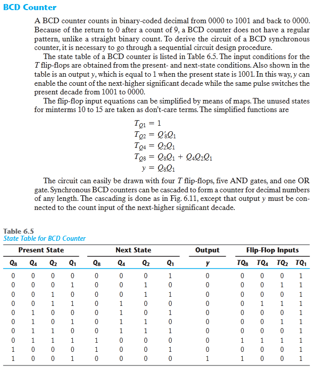
BCD Counter A BCD counter counts in binary-coded decimal from 0000 to 1001 and back to 0000. Because of the return to 0 after a count of 9, a BCD counter does not have a regular pattern, unlike a straight binary count. To derive the circuit of a BCD synchronous counter, it is necessary to go through a sequential circuit design procedure. The state table of a BCD counter is listed in Table 6.5. The input conditions for the T flip-flops are obtained from the present- and next-state conditions. Also shown in the table is an output y, which is equal to 1 when the present state is 1001. In this way, y can enable the count of the next-higher significant decade while the same pulse switches the present decade from 1001 to 0000. The flip-flop input equations can be simplified by means of maps. The unused states for minterms 10 to 15 are taken as don't-care terms. The simplified functions are Tọ1 = 1 To2 = Q&Q1 To4 = Q2Q1 Tos = QsQ1 + Q.Q2lı y = Q&Q1 %3D The circuit can easily be drawn with four T flip-flops, five AND gates, and one OR gate. Synchronous BCD counters can be cascaded to form a counter for decimal numbers of any length. The cascading is done as in Fig. 6.11, except that output y must be con- nected to the count input of the next-higher significant decade.
BCD Counter A BCD counter counts in binary-coded decimal from 0000 to 1001 and back to 0000. Because of the return to 0 after a count of 9, a BCD counter does not have a regular pattern, unlike a straight binary count. To derive the circuit of a BCD synchronous counter, it is necessary to go through a sequential circuit design procedure. The state table of a BCD counter is listed in Table 6.5. The input conditions for the T flip-flops are obtained from the present- and next-state conditions. Also shown in the table is an output y, which is equal to 1 when the present state is 1001. In this way, y can enable the count of the next-higher significant decade while the same pulse switches the present decade from 1001 to 0000. The flip-flop input equations can be simplified by means of maps. The unused states for minterms 10 to 15 are taken as don't-care terms. The simplified functions are Tọ1 = 1 To2 = Q&Q1 To4 = Q2Q1 Tos = QsQ1 + Q.Q2lı y = Q&Q1 %3D The circuit can easily be drawn with four T flip-flops, five AND gates, and one OR gate. Synchronous BCD counters can be cascaded to form a counter for decimal numbers of any length. The cascading is done as in Fig. 6.11, except that output y must be con- nected to the count input of the next-higher significant decade.

Chapter22: Sequence Control
Section: Chapter Questions
Problem 6SQ: Draw a symbol for a solid-state logic element AND.

Related questions

Question
By using the information given in image below design a BCD Counter. You have to provide all the necessary information needed to design this circuit.
Transcribed Image Text:BCD Counter
A BCD counter counts in binary-coded decimal from 0000 to 1001 and back to 0000.
Because of the return to 0 after a count of 9, a BCD counter does not have a regular
pattern, unlike a straight binary count. To derive the circuit of a BCD synchronous
counter, it is necessary to go through a sequential circuit design procedure.
The state table of a BCD counter is listed in Table 6.5. The input conditions for the
T flip-flops are obtained from the present- and next-state conditions. Also shown in the
table is an output y, which is equal to 1 when the present state is 1001. In this way, y can
enable the count of the next-higher significant decade while the same pulse switches the
present decade from 1001 to 0000.
The flip-flop input equations can be simplified by means of maps. The unused states
for minterms 10 to 15 are taken as don't-care terms. The simplified functions are
= 1
To2 = Q&Q1
T94
Tos = Q8Q1 + Q:Q»Q1
y = Q&Q1
The circuit can easily be drawn with four T flip-flops, five AND gates, and one OR
gate. Synchronous BCD counters can be cascaded to form a counter for decimal numbers
of any length. The cascading is done as in Fig. 6.11, except that output y must be con-
nected to the count input of the next-higher significant decade.
Table 6.5
State Table for BCD Counter
Present State
Next State
Output
Flip-Flop Inputs
Q8
Q1
Q8
Q4
Q2
y
TQs TQ4 TQ2 TQ1
1
1
1
0
1
1
1
1
1
1
1.
1
1
1
1.
1.
1.
1.
1.
1
1
1
1.
1
1.
1
1.
1
1
1.
1
1.
1
1.
1.
1
1.
1
1
1
1
1
Expert Solution
This question has been solved!
Explore an expertly crafted, step-by-step solution for a thorough understanding of key concepts.

This is a popular solution!

Trending now
This is a popular solution!

Step by step
Solved in 4 steps with 3 images

Knowledge Booster


Learn more about
Need a deep-dive on the concept behind this application? Look no further. Learn more about this topic, electrical-engineering and related others by exploring similar questions and additional content below.Recommended textbooks for you