Build the circuit shown in the schematic below, using a total of six 1002 resistors in three paths, connected across 5V from the PSB. R4 100 Q R2 100 Q PSB (+ R1 R5 100 Q 5 V 100 Q R3 100 Q R6 100 Q
Build the circuit shown in the schematic below, using a total of six 1002 resistors in three paths, connected across 5V from the PSB. R4 100 Q R2 100 Q PSB (+ R1 R5 100 Q 5 V 100 Q R3 100 Q R6 100 Q

Introductory Circuit Analysis (13th Edition)
13th Edition
ISBN:9780133923605
Author:Robert L. Boylestad
Publisher:Robert L. Boylestad
Chapter1: Introduction
Section: Chapter Questions
Problem 1P: Visit your local library (at school or home) and describe the extent to which it provides literature...

Related questions

Question
How do I do the circuit shown in the schematic in a breadboard
Transcribed Image Text:hal to the Pèsistance in that path, meaning that greater resistance in a path allows less current to flow. In o
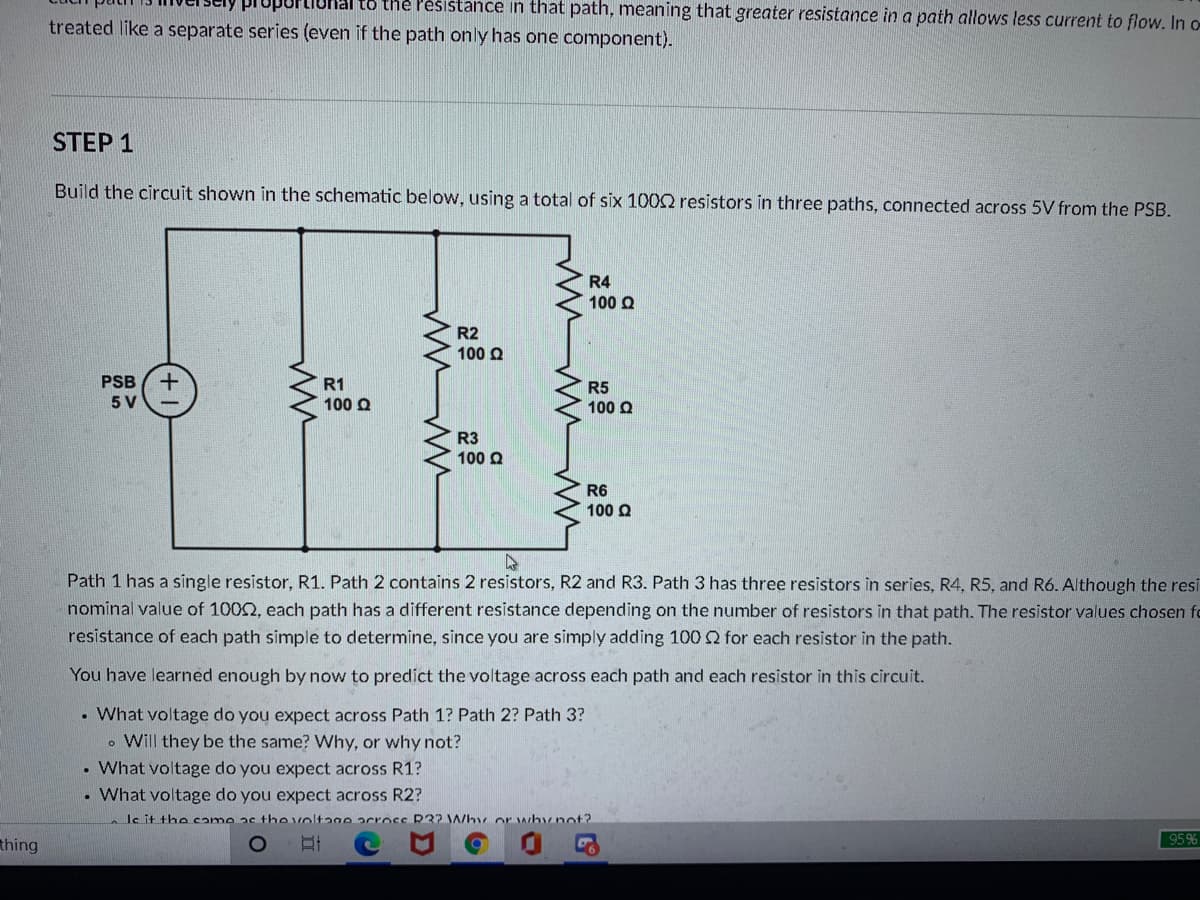
treated like a separate series (even if the path only has one component).
STEP 1
Build the circuit shown in the schematic below, using a total of six 1002 resistors in three paths, connected across 5V from the PSB.
R4
100 Q
R2
100 Q
PSB
R1
100 Q
R5
100 Q
5 V
R3
100 Q
R6
100 Q
Path 1 has a single resistor, R1. Path 2 contains 2 resistors, R2 and R3. Path 3 has three resistors in series, R4, R5, and R6. Although the resi
nominal value of 1002, each path has a different resistance depending on the number of resistors in that path. The resistor values chosen fo
resistance of each path simple to determine, since you are simply adding 100 for each resistor in the path.
You have learned enough by now to predict the voltage across each path and each resistor in this circuit.
• What voltage do you expect across Path 1? Path 2? Path 3?
. Will they be the same? Why, or why not?
• What voltage do you expect across R1?
What voltage do you expect across R2?
le it the came as the voltage acrocc R32 Why or whynot?
thing
95%
Expert Solution
This question has been solved!
Explore an expertly crafted, step-by-step solution for a thorough understanding of key concepts.

This is a popular solution!

Trending now
This is a popular solution!

Step by step
Solved in 2 steps with 1 images

Knowledge Booster


Learn more about
Need a deep-dive on the concept behind this application? Look no further. Learn more about this topic, electrical-engineering and related others by exploring similar questions and additional content below.Recommended textbooks for you
Introductory Circuit Analysis (13th Edition)
Electrical Engineering
ISBN:
9780133923605
Author:
Robert L. Boylestad
Publisher:
PEARSON

Delmar's Standard Textbook Of Electricity
Electrical Engineering
ISBN:
9781337900348
Author:
Stephen L. Herman
Publisher:
Cengage Learning

Programmable Logic Controllers
Electrical Engineering
ISBN:
9780073373843
Author:
Frank D. Petruzella
Publisher:
McGraw-Hill Education
Introductory Circuit Analysis (13th Edition)
Electrical Engineering
ISBN:
9780133923605
Author:
Robert L. Boylestad
Publisher:
PEARSON
Delmar's Standard Textbook Of Electricity
Electrical Engineering
ISBN:
9781337900348
Author:
Stephen L. Herman
Publisher:
Cengage Learning
Programmable Logic Controllers
Electrical Engineering
ISBN:
9780073373843
Author:
Frank D. Petruzella
Publisher:
McGraw-Hill Education

Fundamentals of Electric Circuits
Electrical Engineering
ISBN:
9780078028229
Author:
Charles K Alexander, Matthew Sadiku
Publisher:
McGraw-Hill Education

Electric Circuits. (11th Edition)
Electrical Engineering
ISBN:
9780134746968
Author:
James W. Nilsson, Susan Riedel
Publisher:
PEARSON

Engineering Electromagnetics
Electrical Engineering
ISBN:
9780078028151
Author:
Hayt, William H. (william Hart), Jr, BUCK, John A.
Publisher:
Mcgraw-hill Education,