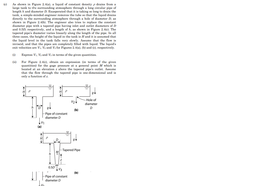
(c) As shown in Figure 2.4(a), a liquid of constant density p drains from a large tank to the surrounding atmosphere through a long circular pipe of length h and diameter D. Exasperated that it is taking so long to drain the tank, a simple-minded engineer removes the tube so that the liquid drains directly to the surrounding atmosphere through a hole of diameter D, as shown in Figure 2.4(b). The engineer also tries to replace the constant diameter pipe with a tapered pipe having inlet and outlet diameters of D and 0.5D, respectively, and a length of h, as shown in Figure 2.4(c). The tapered pipe's diameter varies linearly along the length of the pipe. In all three cases, the height of the liquid in the tank is H and it is assumed that the liquid level in the tank falls very slowly. Assume that the flow is inviscid, and that the pipes are completely filled with liquid. The liquid's exit velocities are V₁, V2 and V3 for Figures 2.4(a), (b) and (c), respectively. (i) Express V₁, V2 and V3 in terms of the given quantities. (ii) For Figure 2.4(c), obtain an expression (in terms of the given quantities) for the gage pressure at a general point M which is located at an elevation z above the tapered pipe's outlet. Assume that the flow through the tapered pipe is one-dimensional and is only a function of z. ↓v₁ (a) TI➜ af -Pipe of constant diameter D Q P 0.5D V₂ V3 -Pipe of constant diameter D (b) -Tapered Pipe (b) -Hole of diameter D
(c) As shown in Figure 2.4(a), a liquid of constant density p drains from a large tank to the surrounding atmosphere through a long circular pipe of length h and diameter D. Exasperated that it is taking so long to drain the tank, a simple-minded engineer removes the tube so that the liquid drains directly to the surrounding atmosphere through a hole of diameter D, as shown in Figure 2.4(b). The engineer also tries to replace the constant diameter pipe with a tapered pipe having inlet and outlet diameters of D and 0.5D, respectively, and a length of h, as shown in Figure 2.4(c). The tapered pipe's diameter varies linearly along the length of the pipe. In all three cases, the height of the liquid in the tank is H and it is assumed that the liquid level in the tank falls very slowly. Assume that the flow is inviscid, and that the pipes are completely filled with liquid. The liquid's exit velocities are V₁, V2 and V3 for Figures 2.4(a), (b) and (c), respectively. (i) Express V₁, V2 and V3 in terms of the given quantities. (ii) For Figure 2.4(c), obtain an expression (in terms of the given quantities) for the gage pressure at a general point M which is located at an elevation z above the tapered pipe's outlet. Assume that the flow through the tapered pipe is one-dimensional and is only a function of z. ↓v₁ (a) TI➜ af -Pipe of constant diameter D Q P 0.5D V₂ V3 -Pipe of constant diameter D (b) -Tapered Pipe (b) -Hole of diameter D

Elements Of Electromagnetics
7th Edition
ISBN:9780190698614
Author:Sadiku, Matthew N. O.
Publisher:Sadiku, Matthew N. O.
ChapterMA: Math Assessment
Section: Chapter Questions
Problem 1.1MA

Related questions

Concept explainers
Question
Transcribed Image Text:(c)
As shown in Figure 2.4(a), a liquid of constant density p drains from a
large tank to the surrounding atmosphere through a long circular pipe of
length h and diameter D. Exasperated that it is taking so long to drain the
tank, a simple-minded engineer removes the tube so that the liquid drains
directly to the surrounding atmosphere through a hole of diameter D, as
shown in Figure 2.4(b). The engineer also tries to replace the constant
diameter pipe with a tapered pipe having inlet and outlet diameters of D
and 0.5D, respectively, and a length of h, as shown in Figure 2.4(c). The
tapered pipe's diameter varies linearly along the length of the pipe. In all
three cases, the height of the liquid in the tank is H and it is assumed that
the liquid level in the tank falls very slowly. Assume that the flow is
inviscid, and that the pipes are completely filled with liquid. The liquid's
exit velocities are V₁, V2 and V3 for Figures 2.4(a), (b) and (c), respectively.
(i) Express V₁, V₂ and V3 in terms of the given quantities.
(ii)
For Figure 2.4(c), obtain an expression (in terms of the given
quantities) for the gage pressure at a general point M which is
located at an elevation z above the tapered pipe's outlet. Assume
that the flow through the tapered pipe is one-dimensional and is
only a function of z.
P
V₁
(a)
H
!!
-Pipe of constant
diameter D
P
0.5D
P
D
V/₂✓
V3
Pipe of constant
diameter D
(b)
-Tapered Pipe
(b)
-Hole of
diameter
D
Expert Solution
This question has been solved!
Explore an expertly crafted, step-by-step solution for a thorough understanding of key concepts.

Step by step
Solved in 3 steps with 3 images

Knowledge Booster


Learn more about
Need a deep-dive on the concept behind this application? Look no further. Learn more about this topic, mechanical-engineering and related others by exploring similar questions and additional content below.Recommended textbooks for you
Elements Of Electromagnetics
Mechanical Engineering
ISBN:
9780190698614
Author:
Sadiku, Matthew N. O.
Publisher:
Oxford University Press

Mechanics of Materials (10th Edition)
Mechanical Engineering
ISBN:
9780134319650
Author:
Russell C. Hibbeler
Publisher:
PEARSON

Thermodynamics: An Engineering Approach
Mechanical Engineering
ISBN:
9781259822674
Author:
Yunus A. Cengel Dr., Michael A. Boles
Publisher:
McGraw-Hill Education
Elements Of Electromagnetics
Mechanical Engineering
ISBN:
9780190698614
Author:
Sadiku, Matthew N. O.
Publisher:
Oxford University Press
Mechanics of Materials (10th Edition)
Mechanical Engineering
ISBN:
9780134319650
Author:
Russell C. Hibbeler
Publisher:
PEARSON
Thermodynamics: An Engineering Approach
Mechanical Engineering
ISBN:
9781259822674
Author:
Yunus A. Cengel Dr., Michael A. Boles
Publisher:
McGraw-Hill Education

Control Systems Engineering
Mechanical Engineering
ISBN:
9781118170519
Author:
Norman S. Nise
Publisher:
WILEY

Mechanics of Materials (MindTap Course List)
Mechanical Engineering
ISBN:
9781337093347
Author:
Barry J. Goodno, James M. Gere
Publisher:
Cengage Learning

Engineering Mechanics: Statics
Mechanical Engineering
ISBN:
9781118807330
Author:
James L. Meriam, L. G. Kraige, J. N. Bolton
Publisher:
WILEY