
Introductory Circuit Analysis (13th Edition)
13th Edition
ISBN: 9780133923605
Author: Robert L. Boylestad
Publisher: PEARSON
expand_more
expand_more
format_list_bulleted
Concept explainers
Question

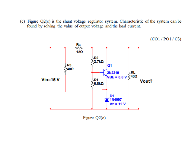
Transcribed Image Text:(c) Figure Q2(c) is the shunt voltage regulator system. Characteristic of the system can be
found by solving the value of output voltage and the load current.
Vin=15 V
R3
400
Rs
120
R2
2.7kQ
R1
6.8kQ
Figure Q2(c)
Q1
2N2219
RL
VBE = 0.6 V400
D1
1N4097
Vz = 12 V
(CO1/PO1/C3)
Vout?
Expert Solution

This question has been solved!
Explore an expertly crafted, step-by-step solution for a thorough understanding of key concepts.
Step by stepSolved in 2 steps with 2 images

Knowledge Booster
Learn more about
Need a deep-dive on the concept behind this application? Look no further. Learn more about this topic, electrical-engineering and related others by exploring similar questions and additional content below.Similar questions
- (b) Discuss the impact of connecting a large capacitor filter across the load in Figure Q1(ii). Use appropriate waveform sketch to aid your discussion. + Vp - Us R2 RL Vs ( (i) (ii) Figure Q1. Single phase half bridge rectifier: (i) with a Thyristor (ii) with a Diodearrow_forward3. A three phase bridge rectifier is supplied by 380 Volt line voltage through a Star/delta connected transformer of which turns ratio is 1. The firing delay angle is a=30° and the load is resistive R=2.2 Ohm. Draw the circuit diagram and mark the followings on this figure : average values of output voltage, the currents and voltages of each transformer leg.arrow_forwardIn the full-wave rectifier circuit of figure 12, the transformer has a turns ratio of 1:2. The transformer primary winding is connected across an AC source of 230V (rms), 50 Hz. The load resistor is 50. For this circuit, determine the DC output voltage (3 significant figures)* Your answerarrow_forward
arrow_back_ios
arrow_forward_ios
Recommended textbooks for you
- Introductory Circuit Analysis (13th Edition)Electrical EngineeringISBN:9780133923605Author:Robert L. BoylestadPublisher:PEARSONDelmar's Standard Textbook Of ElectricityElectrical EngineeringISBN:9781337900348Author:Stephen L. HermanPublisher:Cengage LearningProgrammable Logic ControllersElectrical EngineeringISBN:9780073373843Author:Frank D. PetruzellaPublisher:McGraw-Hill Education
- Fundamentals of Electric CircuitsElectrical EngineeringISBN:9780078028229Author:Charles K Alexander, Matthew SadikuPublisher:McGraw-Hill EducationElectric Circuits. (11th Edition)Electrical EngineeringISBN:9780134746968Author:James W. Nilsson, Susan RiedelPublisher:PEARSONEngineering ElectromagneticsElectrical EngineeringISBN:9780078028151Author:Hayt, William H. (william Hart), Jr, BUCK, John A.Publisher:Mcgraw-hill Education,

Introductory Circuit Analysis (13th Edition)
Electrical Engineering
ISBN:9780133923605
Author:Robert L. Boylestad
Publisher:PEARSON

Delmar's Standard Textbook Of Electricity
Electrical Engineering
ISBN:9781337900348
Author:Stephen L. Herman
Publisher:Cengage Learning

Programmable Logic Controllers
Electrical Engineering
ISBN:9780073373843
Author:Frank D. Petruzella
Publisher:McGraw-Hill Education

Fundamentals of Electric Circuits
Electrical Engineering
ISBN:9780078028229
Author:Charles K Alexander, Matthew Sadiku
Publisher:McGraw-Hill Education

Electric Circuits. (11th Edition)
Electrical Engineering
ISBN:9780134746968
Author:James W. Nilsson, Susan Riedel
Publisher:PEARSON

Engineering Electromagnetics
Electrical Engineering
ISBN:9780078028151
Author:Hayt, William H. (william Hart), Jr, BUCK, John A.
Publisher:Mcgraw-hill Education,