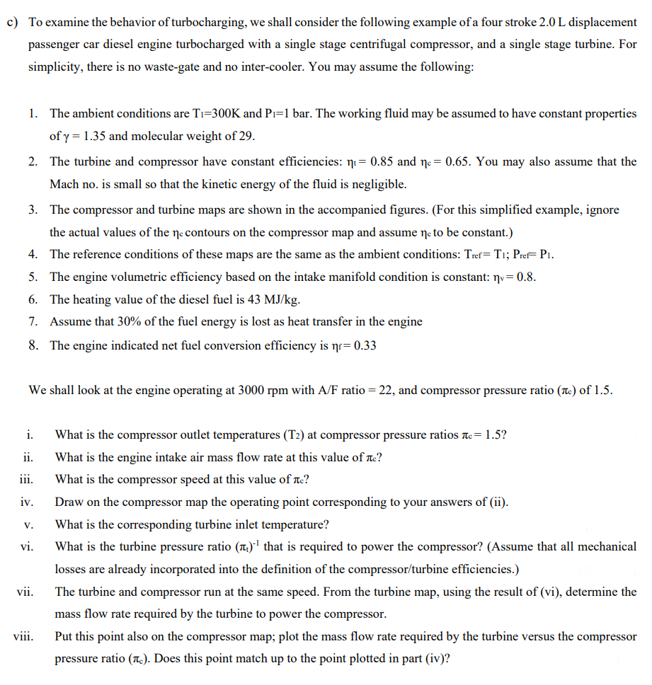
c) To examine the behavior of turbocharging, we shall consider the following example of a four stroke 2.0 L displacement passenger car diesel engine turbocharged with a single stage centrifugal compressor, and a single stage turbine. For simplicity, there is no waste-gate and no inter-cooler. You may assume the following: 1. The ambient conditions are Ti=300K and Pi=1 bar. The working fluid may be assumed to have constant properties of y = 1.35 and molecular weight of 29. 2. The turbine and compressor have constant efficiencies: ni= 0.85 and ne= 0.65. You may also assume that the Mach no. is small so that the kinetic energy of the fluid is negligible. 3. The compressor and turbine maps are shown in the accompanied figures. (For this simplified example, ignore the actual values of the ŋe contours on the compressor map and assume ne to be constant.) 4. The reference conditions of these maps are the same as the ambient conditions: Tref= T1; PreF Pi. 5. The engine volumetric efficiency based on the intake manifold condition is constant: ŋv= 0.8. 6. The heating value of the diesel fuel is 43 MJ/kg. 7. Assume that 30% of the fuel energy is lost as heat transfer in the engine 8. The engine indicated net fuel conversion efficiency is nr= 0.33 We shall look at the engine operating at 3000 rpm with A/F ratio = 22, and compressor pressure ratio (tc) of 1.5. i. What is the compressor outlet temperatures (T2) at compressor pressure ratios nc= 1.5? ii. What is the engine intake air mass flow rate at this value of rc? iii. What is the compressor speed at this value of rc? iv. Draw on the compressor map the operating point corresponding to your answers of (ii). V. What is the corresponding turbine inlet temperature? vi. What is the turbine pressure ratio (1.) that is required to power the compressor? (Assume that all mechanical losses are already incorporated into the definition of the compressor/turbine efficiencies.) vii. The turbine and compressor run at the same speed. From the turbine map, using the result of (vi), determine the mass flow rate required by the turbine to power the compressor. viii. Put this point also on the compressor map; plot the mass flow rate required by the turbine versus the compressor pressure ratio (1.). Does this point match up to the point plotted in part (iv)?
c) To examine the behavior of turbocharging, we shall consider the following example of a four stroke 2.0 L displacement passenger car diesel engine turbocharged with a single stage centrifugal compressor, and a single stage turbine. For simplicity, there is no waste-gate and no inter-cooler. You may assume the following: 1. The ambient conditions are Ti=300K and Pi=1 bar. The working fluid may be assumed to have constant properties of y = 1.35 and molecular weight of 29. 2. The turbine and compressor have constant efficiencies: ni= 0.85 and ne= 0.65. You may also assume that the Mach no. is small so that the kinetic energy of the fluid is negligible. 3. The compressor and turbine maps are shown in the accompanied figures. (For this simplified example, ignore the actual values of the ŋe contours on the compressor map and assume ne to be constant.) 4. The reference conditions of these maps are the same as the ambient conditions: Tref= T1; PreF Pi. 5. The engine volumetric efficiency based on the intake manifold condition is constant: ŋv= 0.8. 6. The heating value of the diesel fuel is 43 MJ/kg. 7. Assume that 30% of the fuel energy is lost as heat transfer in the engine 8. The engine indicated net fuel conversion efficiency is nr= 0.33 We shall look at the engine operating at 3000 rpm with A/F ratio = 22, and compressor pressure ratio (tc) of 1.5. i. What is the compressor outlet temperatures (T2) at compressor pressure ratios nc= 1.5? ii. What is the engine intake air mass flow rate at this value of rc? iii. What is the compressor speed at this value of rc? iv. Draw on the compressor map the operating point corresponding to your answers of (ii). V. What is the corresponding turbine inlet temperature? vi. What is the turbine pressure ratio (1.) that is required to power the compressor? (Assume that all mechanical losses are already incorporated into the definition of the compressor/turbine efficiencies.) vii. The turbine and compressor run at the same speed. From the turbine map, using the result of (vi), determine the mass flow rate required by the turbine to power the compressor. viii. Put this point also on the compressor map; plot the mass flow rate required by the turbine versus the compressor pressure ratio (1.). Does this point match up to the point plotted in part (iv)?

Elements Of Electromagnetics
7th Edition
ISBN:9780190698614
Author:Sadiku, Matthew N. O.
Publisher:Sadiku, Matthew N. O.
ChapterMA: Math Assessment
Section: Chapter Questions
Problem 1.1MA

Related questions

Question
internal combustion engine. please help as much as possible
Transcribed Image Text:c) To examine the behavior of turbocharging, we shall consider the following example of a four stroke 2.0 L displacement
passenger car diesel engine turbocharged with a single stage centrifugal compressor, and a single stage turbine. For
simplicity, there is no waste-gate and no inter-cooler. You may assume the following:
1. The ambient conditions are Tı=300K and Pi=1 bar. The working fluid may be assumed to have constant properties
of y = 1.35 and molecular weight of 29.
2. The turbine and compressor have constant efficiencies: ni= 0.85 and ne= 0.65. You may also assume that the
Mach no. is small so that the kinetic energy of the fluid is negligible.
3. The compressor and turbine maps are shown in the accompanied figures. (For this simplified example, ignore
the actual values of the ne contours on the compressor map and assume ne to be constant.)
4. The reference conditions of these maps are the same as the ambient conditions: Tref= T1; Pref= P1.
5. The engine volumetric efficiency based on the intake manifold condition is constant: nv= 0.8.
6. The heating value of the diesel fuel is 43 MJ/kg.
7. Assume that 30% of the fuel energy is lost as heat transfer in the engine
8. The engine indicated net fuel conversion efficiency is nr= 0.33
We shall look at the engine operating at 3000 rpm with A/F ratio = 22, and compressor pressure ratio (Tc) of 1.5.
i.
What is the compressor outlet temperatures (T2) at compressor pressure ratios Tc= 1.5?
ii.
What is the engine intake air mass flow rate at this value of Tc?
ii.
What is the compressor speed at this value of rc?
iv.
Draw on the compressor map the operating point corresponding to your answers of (ii).
What is the corresponding turbine inlet temperature?
V.
vi.
What is the turbine pressure ratio (a)l that is required to power the compressor? (Assume that all mechanical
losses are already incorporated into the definition of the compressor/turbine efficiencies.)
vii.
The turbine and compressor run at the same speed. From the turbine map, using the result of (vi), determine the
mass flow rate required by the turbine to power the compressor.
viii.
Put this point also on the compressor map; plot the mass flow rate required by the turbine versus the compressor
pressure ratio (.). Does this point match up to the point plotted in part (iv)?
Expert Solution
This question has been solved!
Explore an expertly crafted, step-by-step solution for a thorough understanding of key concepts.

This is a popular solution!

Trending now
This is a popular solution!

Step by step
Solved in 2 steps with 3 images

Knowledge Booster


Learn more about
Need a deep-dive on the concept behind this application? Look no further. Learn more about this topic, mechanical-engineering and related others by exploring similar questions and additional content below.Recommended textbooks for you
Elements Of Electromagnetics
Mechanical Engineering
ISBN:
9780190698614
Author:
Sadiku, Matthew N. O.
Publisher:
Oxford University Press

Mechanics of Materials (10th Edition)
Mechanical Engineering
ISBN:
9780134319650
Author:
Russell C. Hibbeler
Publisher:
PEARSON

Thermodynamics: An Engineering Approach
Mechanical Engineering
ISBN:
9781259822674
Author:
Yunus A. Cengel Dr., Michael A. Boles
Publisher:
McGraw-Hill Education
Elements Of Electromagnetics
Mechanical Engineering
ISBN:
9780190698614
Author:
Sadiku, Matthew N. O.
Publisher:
Oxford University Press
Mechanics of Materials (10th Edition)
Mechanical Engineering
ISBN:
9780134319650
Author:
Russell C. Hibbeler
Publisher:
PEARSON
Thermodynamics: An Engineering Approach
Mechanical Engineering
ISBN:
9781259822674
Author:
Yunus A. Cengel Dr., Michael A. Boles
Publisher:
McGraw-Hill Education

Control Systems Engineering
Mechanical Engineering
ISBN:
9781118170519
Author:
Norman S. Nise
Publisher:
WILEY

Mechanics of Materials (MindTap Course List)
Mechanical Engineering
ISBN:
9781337093347
Author:
Barry J. Goodno, James M. Gere
Publisher:
Cengage Learning

Engineering Mechanics: Statics
Mechanical Engineering
ISBN:
9781118807330
Author:
James L. Meriam, L. G. Kraige, J. N. Bolton
Publisher:
WILEY