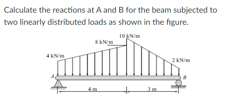
Calculate the reactions at A and B for the beam subjected to two linearly distributed loads as shown in the figure. 10 kN/m 8 kN/m 4 kN/m 2 kN/m B 4 m 3 m


Q: A beam AB is attached to a rocker at A and a pin at B. it is subjected to three forces as shown in…
A:
Q: 1. Determine the reactions at A and B for the beams loaded as shown in Figure (a)-(c) below. Beam…
A:
Q: A beam with overhanging ends supports three concentrated loads of 12 kips, 14 kips, and 16 kips and…
A:
Q: 3. As shown in figure, the intensity of loading on a simply supported beam 10 ft long is given by y…
A:
Q: 10.) Determine the reactions R, and R2 of the beam in the figure shown, loaded with a concentrated…
A: GIVEN DATA A BEAM IS GIVEN SUPPORTED AT TWO POINT WE HAVE TO FIND REACTION AT 1 & 2
Q: Q1) The beam of Example 4.8 is supported as shown. The support at b settles 20 mm, carrying the beam…
A:
Q: Calculate the support reactions at A and B for the beam subjected to the tv linearly distributed…
A: Reaction Ay will be at point A and reaction By will be at point B
Q: The reaction at the support B of the beam shown in below figure is 2 EN 3 kN B 45° 2 m 2 m 2 m 3 m 2…
A:
Q: 1. The cantilever beam in Figure 1 is fixed at A, and is loaded with a distributed load from B to C…
A:
Q: The simply supported beam in the figure is loaded by the counterclockwise Co at B. Draw the shear…
A: To draw SFD and BMD
Q: Mo Wo х |A В C a b
A:
Q: 5. For the beam loaded as shown, calculate the internal axial force, shear force, and bending moment…
A: Let's mark the point E as shown in below figure.
Q: Calculate the support reaction at A and B for thve beam shown in the fiqure betow Take F 700 N. 3M…
A:
Q: 1. Determine the maximum deflection d in a simply supported beam of length L carrying a uniformly…
A:
Q: Calculate the support reactions at A and B for the beam subjected to the two linearly distributed…
A: Given figure
Q: 5. The two 12-ft beams shown in the figure are to be moved horizontally with respect to each other…
A: For solution refer below images.
Q: For the cantilever beam and loading shown below; a-) Calculate the reactions at the fixed end B. 360…
A: Given that , load at A = 1000 N AB =12 m Force per meter on AB = 360 N/m
Q: Statics
A:
Q: Q7: for the figure shown below, calculate the reactions at the point O 30/ 3 kN 15 kN-m B 1.4 kN 1.2…
A:
Q: For the beam shown, find the reactions at the supports and plot the shear-force and bending-moment…
A:
Q: For the simply supported beam shown, derive the Moment and the elastic curve equations in terms of…
A: Given:- F=30kN UDL=20kN/m Integration constants C1=150, C2=70 RA and Rc are…
Q: Problem 3. Problem. The upper beam in figure is supported by a reaction R3 at D and a roller at C…
A:
Q: The beam AB in the figure supports a load which varies uniformly from an intensity of 20 KNim to 120…
A:
Q: With the same loading conditions as in problem a, and to reduce the deflection at C, a roller…
A: Draw a free body diagram showing the reactions acting and each of the supports. Here, RA, RB, and…
Q: 1. The cantilever beam in Figure 1 is fixed at A, and is loaded with a distrib to C and a…
A:
Q: Find the support reactions, draw the free-body diagram of the beams that shows the reactions and the…
A: .
Q: :for the figure shown below, calculate the reactions at the point O 30° 15 kN-m 3 kN A B 1.4 kN F1.2…
A:
Q: A beam is loaded as shown in the figure below. The reaction R2 is equivalent to Blank 1 kN. | 20 kN…
A:
Q: 15 kN 5 kN/m The simply supported beam with a distributed load and couple moment at its center as…
A:
Q: Determine the reactions at A and B shown in Figure below , neglect the weight of beam 400 Ib/ft 200…
A: Given data: - The UDL load acting on the left side of the beam is wl = 200 lb/ft. The UDL load…
Q: A continuous beam ABC wit h two unequal spans, one of length L and one of length 2L, supports a…
A: Indeterminate system An indeterminate system in the one where Number of unknowns are less than the…
Q: 3. (a) Determine the reactions on the beam shown in Figure 3a caused by the rocker at A and the pin…
A: Beam has rocker support at A which works similar to roller support and pin support at B. the…
Q: The beam AB in the figure supports a load which varies from an intensity of 50 KN per linear meter…
A: This numerical is related to the strength of material portion. Concept is used Convert actual…
Q: A beam is loaded as shown in the figure below. The reaction R2 is equivalent to Blank 1 kN. 40 kN |…
A:
Q: Pair of beams (AB) and (CDE) are connected by cable BC and subjected to the concentrated and…
A:
Q: Q/4/.. Draw the shear force and bending moment diagram for the beam and Find the reaction at support…
A: Consider the diagram shown below for the given system.
Q: A beam ABC is simply supported at A and B and has an overhang BC( see figure).The beam is loaded by…
A: given data; ⇒applied load=P ⇒lets take;⇒reaction force at A=RA⇒reaction force at B=RB⇒reaction…
Q: 15.) The beam shown in the figure is supported by a hinge at A and a roller on a 1 to 2 slope at B.…
A: When the load is applied on a simply supported beam it experiences reactions at the supports. This…
Q: A beam 12m long is resting on supports at each end. If the beam carries loads at the positions shown…
A:
Q: 2) For the Simply Supported Beam Carrying Four point loads, as shown in the Figure, (a)…
A:
Q: Wa Wb -х C В А а
A:
Q: 3. Determine the reaction force at A and B for the beam shown in Figure. - 4 - 60) kN/m om
A: Let Ra and Rb are reactions at A and B We will use integration method to solve this…
Q: B 1.5 0.5 0.5 (14 kN) (s0 kN)
A:
Q: Example: Determine the reactions at supports (A) and (B) for the beam loaded as shown in figure…
A: Given: Support reaction at point A is RA and Support reaction at point B is RBH, RBV. F = 73+30 =…
Q: The beam AB in the figure supports a load which varies from an intensity of 50 KN per linear meter…
A:
Q: A beam (AB) is attached to a roller at A and a pin at B. It is subjected to three concentrated…
A:
Q: H.W. 4 / Find the reactions of the simply supported beam shown in Figure below 50 kN 30 kN/m Int.…
A:
Q: 4.20 The beam shown carries vertical concentrated loads. Calculate the reaction at each support.…
A:
Q: QUESTION 4 For the loaded structural beam shown in the Figure, the resultant support reaction at B…
A:
Calculate the reactions at A and B for the beam subjected to two linearly distributed loads as shown in the figure.


Trending now
This is a popular solution!

Step by step
Solved in 2 steps with 4 images

- A fixed-end beam AB supports a uniform load of intensity q = 75 lb/ft acting over part of the span. Assume that EI = 300kip-ft2. Calculate the reactions at A and B. Find the maximum displacement and its location. Repeat part (a) if the distributed load is applied from A to B.The cross section of a bimetallic strip is shown in the figure. Assuming that the moduli of elasticity for metals A and B are EA=168 GPa and EB= 90 GPa, respectively, determine the smaller of the two section moduli for the beam. (Recall that section modulus is equal to bending moment divided by maximum bending stress.) In which material does the maximum stress occur?Two identical, simply supported beams AB and CD are placed so that they cross each other at their midpoints (sec figure). Before the uniform load is applied, the beams just touch each other at the crossing point. Determine the maximum bending moments (mab)max* and (MCD)max beams AB and CD, respectively, due to the uniform load if the intensity of the load is q = 6.4 kN/m and the length of each beam is L = 4 m.
- A beam supporting a uniform load of intensity q throughout its length rests on pistons at points A, C and B (sec figure). The cylinders are filled with oil and are connected by a tube so that the oil pressure on each piston is the same. The pistons at A and B have diameter d1and the piston at C has diameter D2. (a) Determine the ratio of d2to d1so that the largest bending moment in the beam is as small as possible. Under these optimum conditions, what is the largest bending moment Mmaxin the beam? What is the difference in elevation between point C and the end supports?A propped cantilever beam is loaded by a triangular distributed load from A to C (sec figure). The load has a peak intensity q0= 10 lb/ft. The length of the beam is 12 ft. Find support reactions at A and B.A temporary wood flume serving as a channel for irrigation water is shown in the figure. The vertical boards forming the sides of the flume are sunk in the ground, which provides a fixed support. The top of the flume is held by tic rods that are tightened so that there is no deflection of the boards at that point. Thus, the vertical boards may be modeled as a beam AB, supported and loaded as shown in the last part of the figure. Assuming that the thickness t of the boards is 1,5 in., the depth d of the water is 40 in., and the height h to the tie rods is 50 in., what is the maximum bending stress in the boards? Hint: The numerically largest bending moment occurs at the fixed support.
- The wing of a large commercial jet is represented by a simplified prismatic cantilever beam model with uniform load \v and concentrated loads P at the two engine locations (see figure). Find expressions for the tip deflection and rotation at D in terms of \\\ P, L, and EL.A propped cantilever beam is subjected to two triangularly distributed loads, each with a peak load intensity equal to q0(see figure), lind the expressions for reactions at A and C using superposition. Plot shear and moment diagrams.A fixed-end beam AB of a length L is subjected to a uniform load of intensity q acting over the middle region of the beam (sec figure). Obtain a formula for the fixed-end moments MAand MBin terms of the load q, the length L, and the length h of the loaded part of the beam. Plot a graph of the fixed-end moment MAversus the length b of the loaded part of the beam. For convenience, plot the graph in the following nondimensional form: MAqL2/l2versusbL with the ratio b/L varying between its extreme values of 0 and 1. (c) For the special case in which ù = h = L/3, draw the shear-force and bending-moment diagrams for the beam, labeling all critical ordinates.
- Determine the fixed-end moments (MAand MB) and fixed-end forces (R4and Rs) for a beam of length L supporting a triangular load of maximum intensity q0(see figure). Then draw the shear-force and bending-moment diagrams, labeling all critical ordinates.A simple beam AB is subjected to a load in the form of a couple M0 acting at end B (see figure). Determine the angles of rotation A and B at the supports and the deflection at the midpoint.A simple beam AB is subjected to couples M0and 2A0 acting as shown in the figure. Determine the angles of rotation 04and BBat the ends of the beam and the deflection S at point D where the load M0is applied.