Consider a 220-kV transmission system shown in Figure Q2. The per phase the impedances of the lines LO1 and L02 are 2 + j20 and 2.5 + j25 0, respectively. The outputs of the CT and VT are standardized at 5 A and 110 V, respectively. If the maximum load supplied by the line L01 is 100 MVA with a lagging power factor of 0.9, design a three- zone distance-relaying system for the RO distance relay by determining the following: (a) maximum load current (b) CT ratio; (c) VT ratio; (d) impedance measured by relay; (e) load impedance referred to the output side of the sensors; () Stage 1 setting of relay RO; (g) Stage 2 setting of relay R0;
Consider a 220-kV transmission system shown in Figure Q2. The per phase the impedances of the lines LO1 and L02 are 2 + j20 and 2.5 + j25 0, respectively. The outputs of the CT and VT are standardized at 5 A and 110 V, respectively. If the maximum load supplied by the line L01 is 100 MVA with a lagging power factor of 0.9, design a three- zone distance-relaying system for the RO distance relay by determining the following: (a) maximum load current (b) CT ratio; (c) VT ratio; (d) impedance measured by relay; (e) load impedance referred to the output side of the sensors; () Stage 1 setting of relay RO; (g) Stage 2 setting of relay R0;

Power System Analysis and Design (MindTap Course List)
6th Edition
ISBN:9781305632134
Author:J. Duncan Glover, Thomas Overbye, Mulukutla S. Sarma
Publisher:J. Duncan Glover, Thomas Overbye, Mulukutla S. Sarma
Chapter12: Power System Controls
Section: Chapter Questions
Problem 12.18P

Related questions
Question
100%
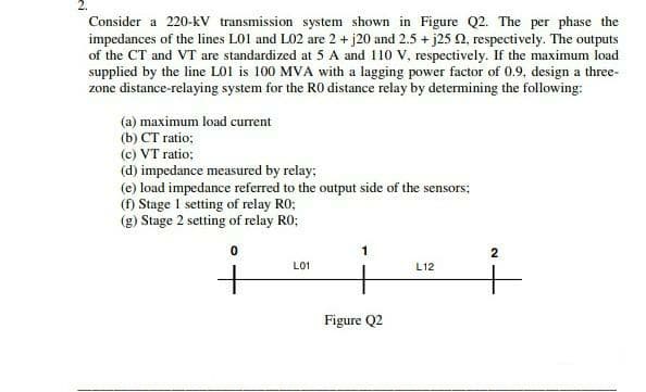
Transcribed Image Text:Consider a 220-kV transmission system shown in Figure Q2. The per phase the
impedances of the lines LO1 and L02 are 2 + j20 and 2.5 + j25 0, respectively. The outputs
of the CT and VT are standardized at 5 A and 110 V, respectively. If the maximum load
supplied by the line LO1 is 100 MVA with a lagging power factor of 0.9, design a three-
zone distance-relaying system for the RO distance relay by determining the following:
(a) maximum load current
(b) CT ratio;
(c) VT ratio;
(d) impedance measured by relay;
(e) load impedance referred to the output side of the sensors:
(f) Stage 1 setting of relay RO;
(g) Stage 2 setting of relay RO;
2
L01
L12
Figure Q2
Expert Solution
This question has been solved!
Explore an expertly crafted, step-by-step solution for a thorough understanding of key concepts.

Step by step
Solved in 4 steps

Knowledge Booster


Learn more about
Need a deep-dive on the concept behind this application? Look no further. Learn more about this topic, electrical-engineering and related others by exploring similar questions and additional content below.Recommended textbooks for you
Power System Analysis and Design (MindTap Course …
Electrical Engineering
ISBN:
9781305632134
Author:
J. Duncan Glover, Thomas Overbye, Mulukutla S. Sarma
Publisher:
Cengage Learning
Power System Analysis and Design (MindTap Course …
Electrical Engineering
ISBN:
9781305632134
Author:
J. Duncan Glover, Thomas Overbye, Mulukutla S. Sarma
Publisher:
Cengage Learning