Consider the bracket shown in Fig-3. If: • F1 - 10 lb @ -90° • a- 2 ft •b- 4 ft • c- 1 ft then, what is the direction of the vertical reaction at point 'A'? 0° 90° 180° O 270°
Consider the bracket shown in Fig-3. If: • F1 - 10 lb @ -90° • a- 2 ft •b- 4 ft • c- 1 ft then, what is the direction of the vertical reaction at point 'A'? 0° 90° 180° O 270°

Mechanics of Materials (MindTap Course List)
9th Edition
ISBN:9781337093347
Author:Barry J. Goodno, James M. Gere
Publisher:Barry J. Goodno, James M. Gere
Chapter1: Tension, Compression, And Shear
Section: Chapter Questions
Problem 1.3.24P: A plane frame is constructed by using a pin connection between segments ABC and CDE. The frame has...

Related questions

Question
Transcribed Image Text:Consider the bracket shown in Fig-3. If:
• F1 = 10 lb @ -90°
• a = 2 ft
• b = 4 ft
• c= 1 ft
then, what is the direction of the vertical reaction at point 'A'?
0°
90°
180°
O 270°
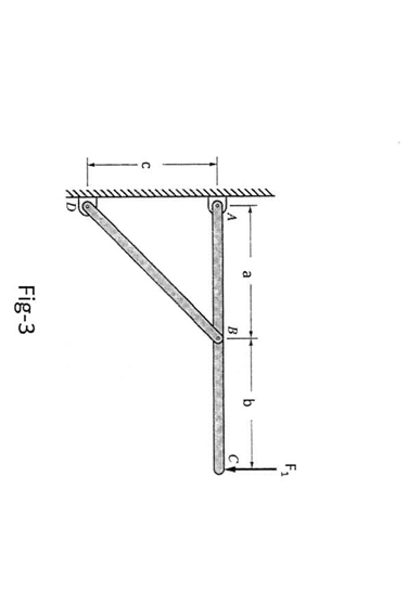
Transcribed Image Text:F,
a
b
Fig-3
Expert Solution
This question has been solved!
Explore an expertly crafted, step-by-step solution for a thorough understanding of key concepts.

This is a popular solution!

Trending now
This is a popular solution!

Step by step
Solved in 2 steps with 2 images

Knowledge Booster


Learn more about
Need a deep-dive on the concept behind this application? Look no further. Learn more about this topic, mechanical-engineering and related others by exploring similar questions and additional content below.Recommended textbooks for you
Mechanics of Materials (MindTap Course List)
Mechanical Engineering
ISBN:
9781337093347
Author:
Barry J. Goodno, James M. Gere
Publisher:
Cengage Learning
Mechanics of Materials (MindTap Course List)
Mechanical Engineering
ISBN:
9781337093347
Author:
Barry J. Goodno, James M. Gere
Publisher:
Cengage Learning