
Concept explainers
Videos
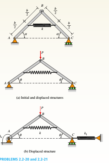
A framework ABC consists of two rigid bars AB and BC. Each having a length b (see the first part of the figure part a). The bars have pin connections at A, B, and C and are joined by a spring of stiffness k. The spring is attached at the midpoints of the bars. The framework has a pin support at A and a roller support al C, and the bars are at an angle a to the horizontal.
When a vertical load P is applied at joint B (see the second part of the figure part a.) the roller support C moves to the right, the spring is stretched, and the angle of the bars decreases from a to the angle ??.
(a) Determine the angle 0 and the increase S in the distance between points A and C. Also find reactions at A and C. (Use the following data: b = 200 mm. ft = 3.2 kN/m. a = 45°. and
P = 50 N.)
(b) Repeat part (a) if a translational spring kt= kll is added at C and a rotational spring kr= kb-l2 is added at A (see figure pan b).
(a)
The angle
Answer to Problem 2.2.20P
The angle
The distance between points A and C,
The reaction at support C
The reaction at support A
Explanation of Solution
Given information:
The length of the rigid bars b = 200 mm
The stiffness of the spring k = 3.2 kN/m
The angle of bars from the horizontal =
The valueof load P = 50 N
Figure: Initial and displaced positions of the framework.
Calculation:
Let us consider the structure in its displaced position. Let us use the free body diagrams of left-hand bars and right-hand bars.
From the free body diagram of left-hand bar,
Reaction at support A,
From the free body diagram of right-hand bar,
From overall FBD of the beams,
We have two expressions for Rc, equating both of the expressions and then substitute expressions for L2, kr, k1, h and
Now,
Let us substitute the numerical values of variables and calculate the values of angle
Solving the above equation gives,
Now, let us compute the reactions at point C and A.
The reaction at point C
And the reaction at point A is
Conclusion: Thus, the angle
The distance between points A and C,
The reaction at support C
The reaction at support A
(b)
The angle
Answer to Problem 2.2.20P
The angle
The distance between points A and C,
The reaction at support C
The reaction at support A
The moment reaction at point A is
Explanation of Solution
Given information:
The length of the rigid bars b = 200 mm
The stiffness of the spring k = 3.2 kN/m
The angle of bars from the horizontal =
The value of load P = 50 N
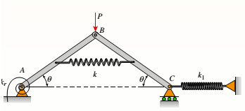
Figure: Initial and displaced positions of the framework.
Calculation:
Let us consider the structure in its displaced position. Let us use the free body diagrams of left-hand bars and right-hand bars.
From the free body diagram of left-hand bar,
Reaction at support A,
From the free body diagram of right-hand bar,
From overall FBD of the beams,
We have two expressions for Rc, equating both of the expressions and then substitute expressions for L2, kr, k1, h and
Now,
Let us substitute the numerical values of variables and calculate the values of angle
Solving the above equation gives,
Now, let us compute the reactions at point C and A.
The reaction at point C,
And the reaction at point A is
Now, moment reaction at point A is,
Conclusion: Thus, the angle
The distance between points A and C,
The reaction at support C
The reaction at support A
The moment reaction at point A is
Want to see more full solutions like this?
Chapter 2 Solutions
Mechanics of Materials (MindTap Course List)


- Two pipe columns (AB, FC) are pin-connected to a rigid beam (BCD), as shown in the figure. Each pipe column has a modulus of E, but heights (L1or L2) and outer diameters (d1or different for each column. Assume the inner diameter of each column is 3/4 of outer diameter. Uniformly distributed downward load q = 2PIL is applied over a distance of 3L/4 along BC, and concentrated load PIA is applied downward at D. (a) Derive a formula for the displacementarrow_forwardA T-frame structure is composed of prismatic beam ABC and nonprismatic column DBF that are joined at B by a friction less pin connection. The beam has a sliding, support at A and the column is pin supported at F (see figure). Beam ABC and. column segment DB have cross-sectional area A; column segment BF has area 2A. The modulus of elasticity E is the same for both members. Load 2P is applied downward at C, and load P acts at D. Find expressions for the downward displacements of column DBF at D (5D) and also at B (arrow_forwardA copper bar AB with a length 25 in. and diameter 2 in. is placed in position at room temperature with a gap of 0.008 in. between end A and a rigid restraint (see figure). The bar is supported at end B by an elastic spring with a spring constant k= 1.2 × 10⁶ lb/in. (a) Calculate the axial compressive stress crcin the bar if the temperature of the bar only rises 50 F. (For copper, use a = 9.6 × 10⁻⁶/ and E = 16 × 106 psi.) (b) What is the force in the spring? (Neglect gravity effects.) (c) Repeat part (a) if k ? 8.arrow_forward
- The assembly shown in the figure consists of a brass core (diameter d:= 0.25 in.) surrounded by a steel shell {inner diameter d2= 0.23 in., outer diameter di= 0.35 in.}. A load .P compresses the core and shell that both have a length L = 4.0 in. The module of elasticity of the brass and steel are Eb=15 X 10fi psi and Es= 30 X 10fi psi, respectively. (a) What load P will compress the assembly by 0.003 in? (b) IF the allowable stress in the steel is 22 ksi and the allowable stress in the brass is 16 ksi. what is the allowable compressive load Pallow? (Suggestion: Use the equations derived in Example 2-8.)arrow_forwardA rigid bar AB having a mass M = 1.0 kg and length L = 0.5 m is hinged at end A and supported at end B by a nylon cord BC (see figure). The record has cross-sectional area A = 30 mm2. length b = 0.25 m. and modulus of elasticity E = 2.1 GPa. If the bar is raised to its maximum height and then released, what is the maximum stress in the cord?arrow_forwardA column ABC is supported at ends A and C and compressed by an axial load P (figure a). Lateral support is provided at point B but only in the plane of the figure; lateral support perpendicular to the plane of the figure is provided only at A and C. The column is constructed of two channel sections (C 6 × 8.2) back to back (see figure b). The modulus of elasticity of the column is E = 29,500 ksi and the proportional limit is 50 ksi. The height of the column is L = 15 ft. Find the allowable value of load P using a factor of safety of 2.5.arrow_forward
- A rigid bar of weight W = SOO N hangs from three equally spaced vertical wines( length L = 150 mm, spacing a = 50 mm J: two of steel and one of aluminum. The wires also support a load P acting on the bar. The diameter of the steel wires is ds= 2 mm, and the diameter of the aluminum wire is d = A mm. a Assume £,=210 GPa and EB« 70 GPa. What load Pallowcan be supported at the mitl-point of the bar (x = a) if the allowable stress in the steel wires is 220 MPa and in the aluminum wire is 80 MPa? (See figure part (b) What is /*,Ikw» if the load is positioned at .v = all1? (See figure part a.) (c) Repeat part (b) if the second and third wires are switched as shown in the figure part b.arrow_forwardAn aluminum bar AD (see figure) has a cross-sectional area of 0.40 in- and is loaded by Forces Pi= 1700 lb, Pz- 1200 lb, and P3 = 1300 lb. The lengths of the segments of the bar are ti = 60 in., b = 24 in.T and c = 36 in. (a) Assuming that the modulus of elasticity is E = 10.4 × 10o psi. calculate the change in length of the bar. Does the bar elongate or shorten? (b) By what amount ^should the load Pibe increased so that the bar does not change in length when the three loads are applied? (c) IF Pzremains at 1300 lb, what revised cross-sectional area For segment AB will result in no change of length when all three loads are applied?arrow_forwardA long, slender bar in the shape of a right circular cone with length L and base diameter d hangs vertically under the action of its own weight (see figure). The weight of the cone is W and the modulus of elasticity of the material is E. Derive a formula for the increase S in the length of the bar due to its own weight. (Assume that the angle of taper of the cone is small.)arrow_forward
- Around brass bar of a diameter d1= 20mm has upset ends each with a diameter d2= 26 mm (see figure). The lengths of the segments of the bar are L1= 0.3 m and L2= 0.1 m. Quarter-circular fillets are used at the shoulders of the bar, and the modulus of elasticity of the brass is E = 100 GPa. If the bar lengthens by 0.12 mm under a tensile load P, what is the maximum stress ??maxin the bar?arrow_forwardA bracket ABCD having a hollow circular cross section consists of a vertical arm AB{L = 6 ft), a horizontal arm BC parallel to the v0 axis, and a horizontal arm CD parallel to the -0 axis (see figure). The arms BC and CD have lengths b}= 3.6 ft and b2= 2,2 ft, respectively. The outer and inner diameters of the bracket are d-, = 7,5 in. and dx= 6,8 in. An inclined load P = 2200 lb acts at point D along line DH. Determine the maximum tensile, compressive, and shear stresses in the vertical armarrow_forwardThe horizontal beam ABC shown in the figure is supported by columns BD and CE. The beam is prevented from moving horizontally by the pin support at end A. Each column is pinned at its upper end to the beam, but at the lower ends, support D is a sliding support and support E is pinned. Both co lu in us arc solid steel bars (E = 30 × 106 psi) of square cross section with width equal to 0.625 in. A load Q acts at distance a from column BD. If the distance a = 12 in., what is the critical value Qcr of the load? If the distance a can be varied between 0 and 40 in., what is the maximum possible value of Qcr? What is the corresponding value of the distance a?arrow_forward
 Mechanics of Materials (MindTap Course List)Mechanical EngineeringISBN:9781337093347Author:Barry J. Goodno, James M. GerePublisher:Cengage Learning