Consider the circuit shown in Figure Q7. The full-wave bridge rectifier is supplied from a transformer that has a secondary winding resistance of 592. When conducting, each diode has a forward voltage drop of 0.7 V, regardless of the current carried. D1 D4 240 V rms 50 Hz D2 D3 RL Figure Q7 (a) The transformer has a turn ratio of 10:1. Find the value of the load resistance, R₁, if the peak voltage across the load is found to be 20.0 V. (b) For a load resistance of 50 and a transformer that gives a peak current in the load of 0.5 A, what is the power dissipated in the load? n:1
Consider the circuit shown in Figure Q7. The full-wave bridge rectifier is supplied from a transformer that has a secondary winding resistance of 592. When conducting, each diode has a forward voltage drop of 0.7 V, regardless of the current carried. D1 D4 240 V rms 50 Hz D2 D3 RL Figure Q7 (a) The transformer has a turn ratio of 10:1. Find the value of the load resistance, R₁, if the peak voltage across the load is found to be 20.0 V. (b) For a load resistance of 50 and a transformer that gives a peak current in the load of 0.5 A, what is the power dissipated in the load? n:1

Introductory Circuit Analysis (13th Edition)
13th Edition
ISBN:9780133923605
Author:Robert L. Boylestad
Publisher:Robert L. Boylestad
Chapter1: Introduction
Section: Chapter Questions
Problem 1P: Visit your local library (at school or home) and describe the extent to which it provides literature...

Related questions
Question
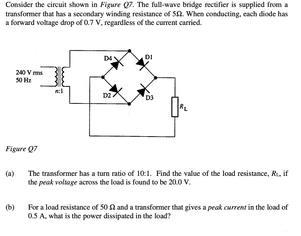
Transcribed Image Text:Consider the circuit shown in Figure Q7. The full-wave bridge rectifier is supplied from a
transformer that has a secondary winding resistance of 52. When conducting, each diode has
a forward voltage drop of 0.7 V, regardless of the current carried.
D1
D4
240 V rms
50 Hz
D2
D3
RL
Figure Q7
(a)
The transformer has a turn ratio of 10:1. Find the value of the load resistance, RL, if
the peak voltage across the load is found to be 20.0 V.
(b)
For a load resistance of 50 2 and a transformer that gives a peak current in the load of
0.5 A, what is the power dissipated in the load?
n:1
Expert Solution
This question has been solved!
Explore an expertly crafted, step-by-step solution for a thorough understanding of key concepts.

Step by step
Solved in 2 steps with 2 images

Knowledge Booster


Learn more about
Need a deep-dive on the concept behind this application? Look no further. Learn more about this topic, electrical-engineering and related others by exploring similar questions and additional content below.Recommended textbooks for you
Introductory Circuit Analysis (13th Edition)
Electrical Engineering
ISBN:
9780133923605
Author:
Robert L. Boylestad
Publisher:
PEARSON

Delmar's Standard Textbook Of Electricity
Electrical Engineering
ISBN:
9781337900348
Author:
Stephen L. Herman
Publisher:
Cengage Learning

Programmable Logic Controllers
Electrical Engineering
ISBN:
9780073373843
Author:
Frank D. Petruzella
Publisher:
McGraw-Hill Education
Introductory Circuit Analysis (13th Edition)
Electrical Engineering
ISBN:
9780133923605
Author:
Robert L. Boylestad
Publisher:
PEARSON
Delmar's Standard Textbook Of Electricity
Electrical Engineering
ISBN:
9781337900348
Author:
Stephen L. Herman
Publisher:
Cengage Learning
Programmable Logic Controllers
Electrical Engineering
ISBN:
9780073373843
Author:
Frank D. Petruzella
Publisher:
McGraw-Hill Education

Fundamentals of Electric Circuits
Electrical Engineering
ISBN:
9780078028229
Author:
Charles K Alexander, Matthew Sadiku
Publisher:
McGraw-Hill Education

Electric Circuits. (11th Edition)
Electrical Engineering
ISBN:
9780134746968
Author:
James W. Nilsson, Susan Riedel
Publisher:
PEARSON

Engineering Electromagnetics
Electrical Engineering
ISBN:
9780078028151
Author:
Hayt, William H. (william Hart), Jr, BUCK, John A.
Publisher:
Mcgraw-hill Education,