A single phase – half wave controlled rectifier with freewheeling diode is supplying a load consisting series connected a resistor and an inductance from a 70.7V (RMS), 50Hz sinusoidal AC source. The firing delay of the thyristor is 90° and the load values are R=10Ω, L=0.1 H. Define the load current expression and draw the load current by calculating for first two periods. And calculate the average values of the load voltage and current.
A single phase – half wave controlled rectifier with freewheeling diode is supplying a load consisting series connected a resistor and an inductance from a 70.7V (RMS), 50Hz sinusoidal AC source. The firing delay of the thyristor is 90° and the load values are R=10Ω, L=0.1 H. Define the load current expression and draw the load current by calculating for first two periods. And calculate the average values of the load voltage and current.

Power System Analysis and Design (MindTap Course List)
6th Edition
ISBN:9781305632134
Author:J. Duncan Glover, Thomas Overbye, Mulukutla S. Sarma
Publisher:J. Duncan Glover, Thomas Overbye, Mulukutla S. Sarma
Chapter4: Transmission Line Parameters
Section: Chapter Questions
Problem 4.2P: The temperature dependence of resistance is also quantified by the relation R2=R1[ 1+(T2T1) ] where...

Related questions
Question
A single phase – half wave controlled rectifier with freewheeling diode is supplying a load consisting
series connected a resistor and an inductance from a 70.7V (RMS), 50Hz sinusoidal AC source.
The firing delay of the thyristor is 90° and the load values are R=10Ω, L=0.1 H. Define the load
current expression and draw the load current by calculating for first two periods. And calculate the
average values of the load voltage and current.
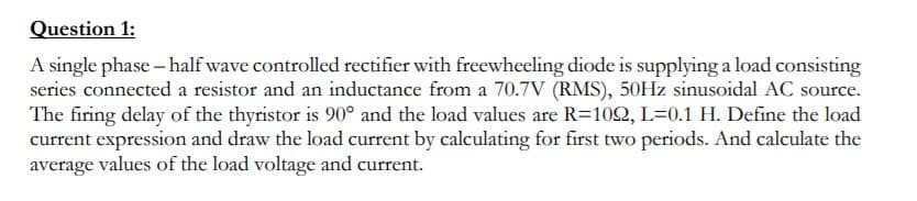
Transcribed Image Text:Question 1:
A single phase – half wave controlled rectifier with freewheeling diode is supplying a load consisting
series connected a resistor and an inductance from a 70.7V (RMS), 50HZ sinusoidal AC source.
The firing delay of the thyristor is 90° and the load values are R=102, L=0.1 H. Define the load
current expression and draw the load current by calculating for first two periods. And calculate the
average values of the load voltage and current.
Expert Solution
This question has been solved!
Explore an expertly crafted, step-by-step solution for a thorough understanding of key concepts.

This is a popular solution!

Trending now
This is a popular solution!

Step by step
Solved in 6 steps with 2 images

Knowledge Booster


Learn more about
Need a deep-dive on the concept behind this application? Look no further. Learn more about this topic, electrical-engineering and related others by exploring similar questions and additional content below.Recommended textbooks for you
Power System Analysis and Design (MindTap Course …
Electrical Engineering
ISBN:
9781305632134
Author:
J. Duncan Glover, Thomas Overbye, Mulukutla S. Sarma
Publisher:
Cengage Learning


Electricity for Refrigeration, Heating, and Air C…
Mechanical Engineering
ISBN:
9781337399128
Author:
Russell E. Smith
Publisher:
Cengage Learning
Power System Analysis and Design (MindTap Course …
Electrical Engineering
ISBN:
9781305632134
Author:
J. Duncan Glover, Thomas Overbye, Mulukutla S. Sarma
Publisher:
Cengage Learning
Electricity for Refrigeration, Heating, and Air C…
Mechanical Engineering
ISBN:
9781337399128
Author:
Russell E. Smith
Publisher:
Cengage Learning

Delmar's Standard Textbook Of Electricity
Electrical Engineering
ISBN:
9781337900348
Author:
Stephen L. Herman
Publisher:
Cengage Learning