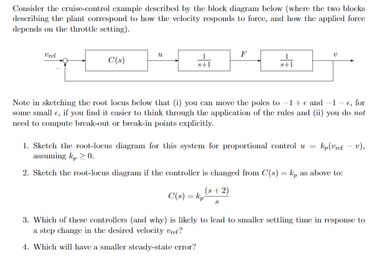
Consider the cruise-control example described by the block diagram below (where the two blocks describing the plant correspond to how the velocity responds to force, and how the applied force depends on the throttle setting). Vref F C(s) s+1 s+1 Note in sketching the root locus below that (i) you can move the poles to –1+e and –1 – €, for some small e, if you find it casier to think through the application of the rules and (ii) you do not need to compute break-out or break-in points explicitly. 1. Sketch the root-locus diagram for this system for proportional control u = kp(vref – v), assuming k, > 0. 2. Sketch the root-locus diagram if the controller is changed from C(s) = k, as above to: (s+2) C(s) = kp- 3. Which of these controllers (and why) is likely to lead to smaller settling time in response to a step change in the desired velocity vref? 4. Which will have a smaller steady-state error?
Consider the cruise-control example described by the block diagram below (where the two blocks describing the plant correspond to how the velocity responds to force, and how the applied force depends on the throttle setting). Vref F C(s) s+1 s+1 Note in sketching the root locus below that (i) you can move the poles to –1+e and –1 – €, for some small e, if you find it casier to think through the application of the rules and (ii) you do not need to compute break-out or break-in points explicitly. 1. Sketch the root-locus diagram for this system for proportional control u = kp(vref – v), assuming k, > 0. 2. Sketch the root-locus diagram if the controller is changed from C(s) = k, as above to: (s+2) C(s) = kp- 3. Which of these controllers (and why) is likely to lead to smaller settling time in response to a step change in the desired velocity vref? 4. Which will have a smaller steady-state error?

Power System Analysis and Design (MindTap Course List)
6th Edition
ISBN:9781305632134
Author:J. Duncan Glover, Thomas Overbye, Mulukutla S. Sarma
Publisher:J. Duncan Glover, Thomas Overbye, Mulukutla S. Sarma
Chapter12: Power System Controls
Section: Chapter Questions
Problem 12.14P

Related questions
Question
Transcribed Image Text:Consider the cruise-control example described by the block diagram below (where the two blocks
describing the plant correspond to how the velocity responds to force, and how the applied force
depends on the throttle setting).
Vref
F
1
C(s)
s+1
Note in sketching the root locus below that (i) you can move the poles to -1+€ and –1 – €, for
some small e, if you find it easier to think through the application of the rules and (ii) you do not
need to compute break-out or brecak-in points explicitly.
1. Sketch the root-locus diagram for this system for proportional control u =
assuming k, > 0.
kip(Vref = v),
2. Sketch the root-locus diagram if the controller is changed from C(s) = k, as above to:
(s + 2)
C(s) = kp-
3. Which of these controllers (and why) is likely to lead to smaller settling time in response to
a step change in the desired velocity vref?
4. Which will have a smaller steady-state error?
Expert Solution
This question has been solved!
Explore an expertly crafted, step-by-step solution for a thorough understanding of key concepts.

This is a popular solution!

Trending now
This is a popular solution!

Step by step
Solved in 6 steps with 9 images

Recommended textbooks for you
Power System Analysis and Design (MindTap Course …
Electrical Engineering
ISBN:
9781305632134
Author:
J. Duncan Glover, Thomas Overbye, Mulukutla S. Sarma
Publisher:
Cengage Learning
Power System Analysis and Design (MindTap Course …
Electrical Engineering
ISBN:
9781305632134
Author:
J. Duncan Glover, Thomas Overbye, Mulukutla S. Sarma
Publisher:
Cengage Learning