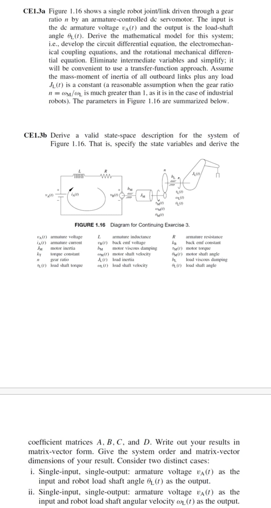
CE1.3a Figure 1.16 shows a single robot joint/link driven through a gear ratio n by an armature-controlled de servomotor. The input is the de armature voltage vA(1) and the output is the load-shaft angle OL(1). Derive the mathematical model for this system; i.e., develop the circuit differential equation, the electromechan- ical coupling equations, and the rotational mechanical differen- tial equation. Eliminate intermediate variables and simplify; it will be convenient to use a transfer-function approach. Assume the mass-moment of inertia of all outboard links plus any load JL(1) is a constant (a reasonable assumption when the gear ratio n = Wm/wr is much greater than 1, as it is in the case of industrial robots). The parameters in Figure 1.16 are summarized below. CE1.3b Derive a valid state-space description for the system of Figure 1.16. That is, specify the state variables and derive the ww by JM (1) FIGURE 1.16 Diagram for Continuing Exercise 3. VA(1) armature voltage ia(1) armature current JM kT armature inductance R armature resistance vg (1) back emf voltage bM wM(1) motor shaft velocity L(1) load inertia On (1) load shaft velocity back emf constant kB TM(1) motor torque motor inertia motor viscous damping OM(1) motor shaft angle load viscous damping torque constant gear ratio L(1) load shaft torque OL(1) load shaft angle coefficient matrices A, B, C, and D. Write out your results in matrix-vector form. Give the system order and matrix-vector dimensions of your result. Consider two distinct cases: i. Single-input, single-output: armature voltage VA (1) as the input and robot load shaft angle OL(1) as the output. ii. Single-input, single-output: armature voltage VA(1) as the input and robot load shaft angular velocity wr(t) as the output.
CE1.3a Figure 1.16 shows a single robot joint/link driven through a gear ratio n by an armature-controlled de servomotor. The input is the de armature voltage vA(1) and the output is the load-shaft angle OL(1). Derive the mathematical model for this system; i.e., develop the circuit differential equation, the electromechan- ical coupling equations, and the rotational mechanical differen- tial equation. Eliminate intermediate variables and simplify; it will be convenient to use a transfer-function approach. Assume the mass-moment of inertia of all outboard links plus any load JL(1) is a constant (a reasonable assumption when the gear ratio n = Wm/wr is much greater than 1, as it is in the case of industrial robots). The parameters in Figure 1.16 are summarized below. CE1.3b Derive a valid state-space description for the system of Figure 1.16. That is, specify the state variables and derive the ww by JM (1) FIGURE 1.16 Diagram for Continuing Exercise 3. VA(1) armature voltage ia(1) armature current JM kT armature inductance R armature resistance vg (1) back emf voltage bM wM(1) motor shaft velocity L(1) load inertia On (1) load shaft velocity back emf constant kB TM(1) motor torque motor inertia motor viscous damping OM(1) motor shaft angle load viscous damping torque constant gear ratio L(1) load shaft torque OL(1) load shaft angle coefficient matrices A, B, C, and D. Write out your results in matrix-vector form. Give the system order and matrix-vector dimensions of your result. Consider two distinct cases: i. Single-input, single-output: armature voltage VA (1) as the input and robot load shaft angle OL(1) as the output. ii. Single-input, single-output: armature voltage VA(1) as the input and robot load shaft angular velocity wr(t) as the output.

Introductory Circuit Analysis (13th Edition)
13th Edition
ISBN:9780133923605
Author:Robert L. Boylestad
Publisher:Robert L. Boylestad
Chapter1: Introduction
Section: Chapter Questions
Problem 1P: Visit your local library (at school or home) and describe the extent to which it provides literature...

Related questions

Question
100%
Transcribed Image Text:CE1.3a Figure 1.16 shows a single robot joint/link driven through a gear
ratio n by an armature-controlled de servomotor. The input is
the de armature voltage va(t) and the output is the load-shaft
angle OL(t). Derive the mathematical model for this system;
i.e., develop the circuit differential equation, the electromechan-
ical coupling equations, and the rotational mechanical differen-
tial equation. Eliminate intermediate variables and simplify; it
will be convenient to use a transfer-function approach. Assume
the mass-moment of inertia of all outboard links plus any load
JL(1) is a constant (a reasonable assumption when the gear ratio
n = wm/wr_ is much greater than 1, as it is in the case of industrial
robots). The parameters in Figure 1.16 are summarized below.
CE1.3b Derive a valid state-space description for the system of
Figure 1.16. That is, specify the state variables and
eriv
the
R
ww
bM
V(f)
JM
(1)
(1)
FIGURE 1.16 Diagram for Continuing Exercise 3.
armature resistance
back emf constant
L.
v'B (1) back emf voltage
bM
OM(1) motor shaft velocity
JL(1) load inertia
WL(1t) load shaft velocity
VA(1) armature voltage
armature inductance
iA(1) armature current
kB
JM
kT
motor inertia
motor viscous damping
TM(1) motor torque
torque constant
gear ratio
TL(1) load shaft torque
OM(1) motor shaft angle
load viscous damping
OL (1) load shaft angle
coefficient matrices A, B, C, and D. Write out your results in
matrix-vector form. Give the system order and matrix-vector
dimensions of your result. Consider two distinct cases:
i. Single-input, single-output: armature voltage vA (1) as the
input and robot load shaft angle O(t) as the output.
ii. Single-input, single-output: armature voltage vA(t) as the
input and robot load shaft angular velocity w(1) as the output.
Expert Solution
This question has been solved!
Explore an expertly crafted, step-by-step solution for a thorough understanding of key concepts.

This is a popular solution!

Trending now
This is a popular solution!

Step by step
Solved in 3 steps

Knowledge Booster


Learn more about
Need a deep-dive on the concept behind this application? Look no further. Learn more about this topic, electrical-engineering and related others by exploring similar questions and additional content below.Recommended textbooks for you
Introductory Circuit Analysis (13th Edition)
Electrical Engineering
ISBN:
9780133923605
Author:
Robert L. Boylestad
Publisher:
PEARSON

Delmar's Standard Textbook Of Electricity
Electrical Engineering
ISBN:
9781337900348
Author:
Stephen L. Herman
Publisher:
Cengage Learning

Programmable Logic Controllers
Electrical Engineering
ISBN:
9780073373843
Author:
Frank D. Petruzella
Publisher:
McGraw-Hill Education
Introductory Circuit Analysis (13th Edition)
Electrical Engineering
ISBN:
9780133923605
Author:
Robert L. Boylestad
Publisher:
PEARSON
Delmar's Standard Textbook Of Electricity
Electrical Engineering
ISBN:
9781337900348
Author:
Stephen L. Herman
Publisher:
Cengage Learning
Programmable Logic Controllers
Electrical Engineering
ISBN:
9780073373843
Author:
Frank D. Petruzella
Publisher:
McGraw-Hill Education

Fundamentals of Electric Circuits
Electrical Engineering
ISBN:
9780078028229
Author:
Charles K Alexander, Matthew Sadiku
Publisher:
McGraw-Hill Education

Electric Circuits. (11th Edition)
Electrical Engineering
ISBN:
9780134746968
Author:
James W. Nilsson, Susan Riedel
Publisher:
PEARSON

Engineering Electromagnetics
Electrical Engineering
ISBN:
9780078028151
Author:
Hayt, William H. (william Hart), Jr, BUCK, John A.
Publisher:
Mcgraw-hill Education,