Consider the U-tube manometer shown in the figure. Both ends of the U-tube manometer is open to atmospheric pressure. The left and right arm of the manometer has a cross-sectional area A1 = 8 cm2 and A1 = 4 cm2, respectively. The left figure illustrates the U-tube when mercury (ρHg =13.6 g⁄ cm3 ) is poured into it. The right figure shows the U-tube manometer when 90.0 g of water is poured in the right arm. (a) Determine the length of the water column in the right arm of the manometer and (b) the distance h the mercury rise in the left arm of the manometer.
Consider the U-tube manometer shown in the figure. Both ends of the U-tube manometer is open to atmospheric pressure. The left and right arm of the manometer has a cross-sectional area A1 = 8 cm2 and A1 = 4 cm2, respectively. The left figure illustrates the U-tube when mercury (ρHg =13.6 g⁄ cm3 ) is poured into it. The right figure shows the U-tube manometer when 90.0 g of water is poured in the right arm. (a) Determine the length of the water column in the right arm of the manometer and (b) the distance h the mercury rise in the left arm of the manometer.

Solid Waste Engineering
3rd Edition
ISBN:9781305635203
Author:Worrell, William A.
Publisher:Worrell, William A.
Chapter4: Mechanical Processes
Section: Chapter Questions
Problem 4.20P

Related questions

Question
100%
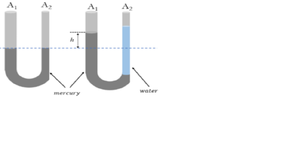
Consider the U-tube manometer shown in the figure. Both ends of the U-tube manometer is open to atmospheric pressure. The left and right arm of the manometer has a cross-sectional area A1 = 8 cm2 and A1 = 4 cm2, respectively. The left figure illustrates the U-tube when mercury (ρHg =13.6 g⁄ cm3 ) is poured into it. The right figure shows the U-tube manometer when 90.0 g of water is poured in the right arm. (a) Determine the length of the water column in the right arm of the manometer and (b) the distance h the mercury rise in the left arm of the manometer.
Transcribed Image Text:A
UU
A2
A1
A2
water
FFmercury
Expert Solution
This question has been solved!
Explore an expertly crafted, step-by-step solution for a thorough understanding of key concepts.

This is a popular solution!

Trending now
This is a popular solution!

Step by step
Solved in 3 steps with 3 images

Knowledge Booster


Learn more about
Need a deep-dive on the concept behind this application? Look no further. Learn more about this topic, civil-engineering and related others by exploring similar questions and additional content below.Recommended textbooks for you
Solid Waste Engineering
Civil Engineering
ISBN:
9781305635203
Author:
Worrell, William A.
Publisher:
Cengage Learning,
Solid Waste Engineering
Civil Engineering
ISBN:
9781305635203
Author:
Worrell, William A.
Publisher:
Cengage Learning,