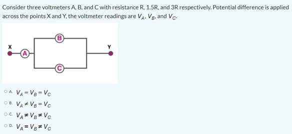
Consider three voltmeters A, B, and C with resistance R, 1.51 across the points X and Y, the voltmeter readings are VA. V8 B) A) OA VA= V8 = Vc OB V. Ve= Yc


Q: Calculate the voltage Vi and the current Ii for the following two cases where the resistance is…
A:
Q: (b) 50 2 shown in the Figure Q11(b). (i) Find the equivalent resistance across AB. (ii) Find the…
A:
Q: A battery has an emf of 15.0 V. The terminal voltage of the battery is 11.6 V when it isdelivering…
A: Given information: The EMF of a battery (ε) = 15.0 V The terminal voltage of the battery (V) = 11.6…
Q: What is the value of resistor R in the figure(Figure 1) if ΔV=7V and I=4A? Express your answer…
A: Given information:Current through the circuit (I) = 4 APotential difference across the circuit (V) =…
Q: What are the expected readings of the following in the figure below? (R = 5.80 N, AV = 6.50 V) A R…
A: The circuit diagram for the given problem:
Q: 13. In the circuit segment below, all internal resistances are r= 2 o and all other resis- tances…
A:
Q: PROBLEM 4: How much electrical energy is converted to thermal energy in 2.00 hrs by an electrical…
A: Hello. Since you have posted multiple questions and not specified which question needs to be solved,…
Q: The four resistors in the figure have an equivalent resistance of 12 2. The resistances are as…
A:
Q: A 58 F capacitor and a 471 resistor are connected to a battery of voltage 7 V as shown in the…
A:
Q: What are the expected readings of the following in the figure below? (R = 8.00 n, AV = 5.20 V) R AV…
A: From Nodal analysis…
Q: A circuit has resistors R1 = 353 N and R2 = 125 2, and two R2 batteries V = 72.0 V and V, = 18.0 V .…
A:
Q: wwwwww- a •b n the arrangement of the resistors shown in the figure, all resistors have identical…
A: All resistors have identical resistance R, we have to have to find equivalent resistance R between a…
Q: Two resistors R, and R2 are wired as shown in the figure. Calculate the electric power for R2, given…
A:
Q: Consider the circuit 7 2 ww 13→ 4 V ww- 12 6 V 10 V 3 2 ww ww Find i1. Answer in units of A.
A:
Q: What are the expected readings of the ammeter and voltmeterfor the circuit in Figure P18.65?
A: Consider the circuit diagram for the nodal analysis. Consider the potential at node A be V.
Q: Power watt? A 3.02 resistor is connected to a non-ideal source with internal resistancer =1.00 and…
A: Given: External resistance, R = 3Ω Internal resistance, r = 1 Ω Emf ε = 16 V Potential measured by…
Q: Complete the R-I-V-P Table of the network of resistors above. I (Amps) V (Volts) P (Watt) R (Q) 10 R
A: Given:- The resistance in the given figure are R1 = 10 ohm R2= 5 ohm R3= 20 ohm R4 = 5ohm Find:-…
Q: An auto mechanic needs to determine the emf and internal resistance of an old battery. He performs…
A: Emf=11.8v Current=17.7A
Q: For the circuit shown, where = 12 V andr310, the potential difference (in V) across the 10 resistor…
A: Given E=12Vμ=1Ω
Q: What are the expected readings of the following in the figure below? (R = 9.30 N, AV = 6.20 V) R Δν…
A:
Q: Two wires A and B made of the same material and having the same lengths are connected across the…
A:
Q: R,=R_ R,=R R;=R R=R R3=2R
A: Voltage across R3 is V = 8V
Q: The following electric circuit consists of a power source, two ammeters (WandO , two resistors (R…
A: We are going to use Ohm's law to find the voltage across the resistance R2. Also, we have to apply…
Q: What are the expected readings of the following in the figure below? (R = 5.80 N, AV = 6.50 V) A R…
A: The current does not flow through the ideal voltmeter, so it will act as an open circuit. There is…
Q: What is the equivalent resistance between points a and b in (Figure 1)? Express your answer in ohms.…
A:
Q: What are the expected readings of the following in the figure below? (R = 5.50 0, AV = 6.70 V) R ΔVν…
A:
Q: What are the expected readings of the following in the figure below? (R = 7.60 0, AV = 5.00 V) R Δν…
A: A). ideal ammeter I= 0.327MA B) ideal voltmeter V=0.5V C).ideal ammeter i =0.93Ma Ideal…
Q: Find the potential difference across each resistor the figure below. (R, = 4.60 N, R, = 4.20 N, R2 =…
A: Given:R1 = 4.60 ohm R2 = 4.20 ohm R3 = 2.80 ohm R4 = 1.80 ohm
Q: In the RC circuit shown below, the capacitor is initially uncharged. After the switch is closed, it…
A: Resistance of resistor: R = 300 kΩ Charge on capacitor: Q = 28% of maximum charge Qmax at time: t =…
Q: What are the expected readings of the following in the figure below? (R = 7.10 0, AV = 6.70 V) A AV…
A:
Q: What does the voltmeter read? For the circuit shown in the figure (Figure 1) both meters are…
A:
Q: What are the expected readings of the following in the figure below? (R = 5.60 N, AV = 6.30 V) R AV…
A: Given: The resistance R=5.6 Ω The voltage ∆V=6.3 volt
Q: 6. Find the voltage across the battery for the following circuit. Note: The battery corresponds to…
A: In this question we have to find the voltage across the battery. Please give positive feedback if…
Q: 16. What is the equivalent resistance of each group of resistors? a. b. C. 22 32 wW w WW 22 32 2Ω 3Ω…
A: Resistors are electronic components which resist the flow of current in a circuit. Ohm's Law…
Q: R= 1.50 ohms 0.50 ohms 10.0V A real battery is connected to resistor R as shown. Calculate the…
A: Given data: Load resistance (R) = 1.50 Ω Internal resistance (r) = 0.50 Ω Battery emf (ε) = 10.0 V…
Q: Two identical resistors ® are connected in parallel and then wired in series to a 40 Ω resistor. If…
A: Given: The Total equivalent resistance = 55Ω The Resistor used in a series = 40Ω
Q: In Figure 7.92, the ammeter reads 2.0 A and the volmeter reads 2.0 V. Use this information to find…
A: (a) The current I1 passing through the following circuit in clock-wise direction. The current is…
Q: What are the expected readings of the following in the figure below? (R = 9.50 N, AV = 6.50 V) R AV…
A:
Q: R V, Rw RA R V. 2 Rw
A:
Q: In the following Figure, the current in resistance R, is i,= 14A and the resistances are R, =R, = R;…
A:
Q: Resistor 1 is 3.8 ohms, resistor 2 is 8.4 ohms and resistor 3 is 7.7 ohms. The ammeter reads 8.9 A.…
A: Resistor 1 is 3.8 ohms, resistor 2 is 8.4 ohms and resistor 3 is 7.7 ohms. The ammeter reads 8.9 A…
Q: What are the expected readings of the following in the figure below? (R = 6.70 N, Av = 5.30 V) R AV…
A: We will use KVL and KCL for the three loops and will find current through ammeter.
Q: What are the expected readings of (a) the ideal ammeter and (b) the ideal voltmeter in Figure?
A:
Q: R1 100KO V1 R2 12V 300KO Determine: a. The theoretical voltage across R2 b. The actual voltage…
A:
Q: A circuit has resistors R¡ = 353 2 and R2 = 125 2, and two batteries V = 72.0 V and V, = 18.0 V. The…
A:
Q: 27 In which circuit shown below could the readings of voltmeters V, and V, and ammeter A be correct?…
A:

Step by step
Solved in 2 steps with 1 images


- In the given circuit, the resistances of each resistor is 5 Ohm. The ideal batteries have EMFS E1= 9V and E2 = 17 V. What is the potential at point P?If you wish to take a picture of a bullet traveling at 500 m/s, then a very brief flash of light produced by an RC discharge through a flash tube can limit blurring. Assuming 1.00 mm of motion during one RC constant is acceptable,and given that the flash is driven by a 600-μF capacitor, what is the resistance in the flash tube?In the circuit below, the capacitor starts out uncharged. The resistance is R = 118 Ω, capacitance is C = 0.0647 F, and the battery emf is 16.7 V. What is the charge (Q) on the capacitor at a time of t = 3.72 seconds after the switch is closed?
- Consider an electric diagram in the figure. When the switch in the circuit on the right is open, the voltmeter V reads 3.78 V. When the switch is closed, the voltmeter reading drops to 3.45 V, and the ammeter A reads 8.83 A. What is the battery internal resistance r (in Ω)?If a voltmeter that is ideal is connected to measure the voltage across the 83.0-kΩ resistor, what is its reading? Enter the absolute value of the reading. (in image, x = 8.20 V)For the circuit shown in Fig.1 below, C1 = 5μF, C2 = 4μF, C3 = 6μF and ∆V = 65V. Find:(a) the equivalent capacitance, (b) the charge on each capacitor and (c) the potential differenceacross each capacitor.Figure 1: Problem 2.Problem 3For the circuit shown in Fig.2 below, determine the resistance R such that the current in R is0.50 A, with the sense from a to b.Figure 2: Problem 2.Problem 4A straight wire of length 0.40 m, carrying current I = 7.0 A is oriented at angle θ = 27◦ toa uniform magnetic field B = 1.2 T. The field is in the positive x-direction. Determine themagnitude and direction of the magnetic force on the wire.1
- An uncharged capacitor and a resistor are connected in seriesto a source of emf. If ε = 9.00 V, C = 20.0 µF, and R = 1.00 x10² Ω, find (a) the time constant of the circuit, (b) the maximumcharge on the capacitor, and (c) the charge on thecapacitor after one time constant.In the figure R1 = 2.11 Ω, R2 = 5.01 Ω, and the battery is ideal. What value of R3 maximizes the dissipation rate in resistance 3?If E = 7.50V and r=0.45Ω, find the minimum value of the voltmeter resistance RV for which the voltmeter reading is within 1.0% of the emf of the battery.
- A real battery consists of an emf, ?= 9.00V and has an internal resistance, r = 1.50Ω. The battery is connected in series with an ammeter, a load resistor of R = 3.00Ω, and an open switch. Determine the potential difference measured by the voltmeter.The capacitance in the curcuit is C = 0.3μF, the total resistance is R=20kQ and the battery emf is 12 V. Determine the time is takes for the charge the capacitor could acquire, to reach 99% of max value.A capacitor with a capacitance of 3.5 uF is initially uncharged. It is connected in series with a switch of negligible resistance, a resistor with a resistance of 10.5 kOhm, and a battery that has a potential difference of 105V. (a) Immediately after the switch is closed, what is the voltage drop VC, in volts, across the capacitor? (b) Immediately after the switch is closed, what is the voltage drop VR, in volts, across the resistor? (c) Immediately after the switch is closed, what is the current, in amperes, through the resistor? (d) Find an expression for the time after the switch is closed when the current in the resistor equals half its maximum value. (e) What is the charge Q, in microcoulombs, on the capacitor when the current in the resistor equals one half its maximum value.