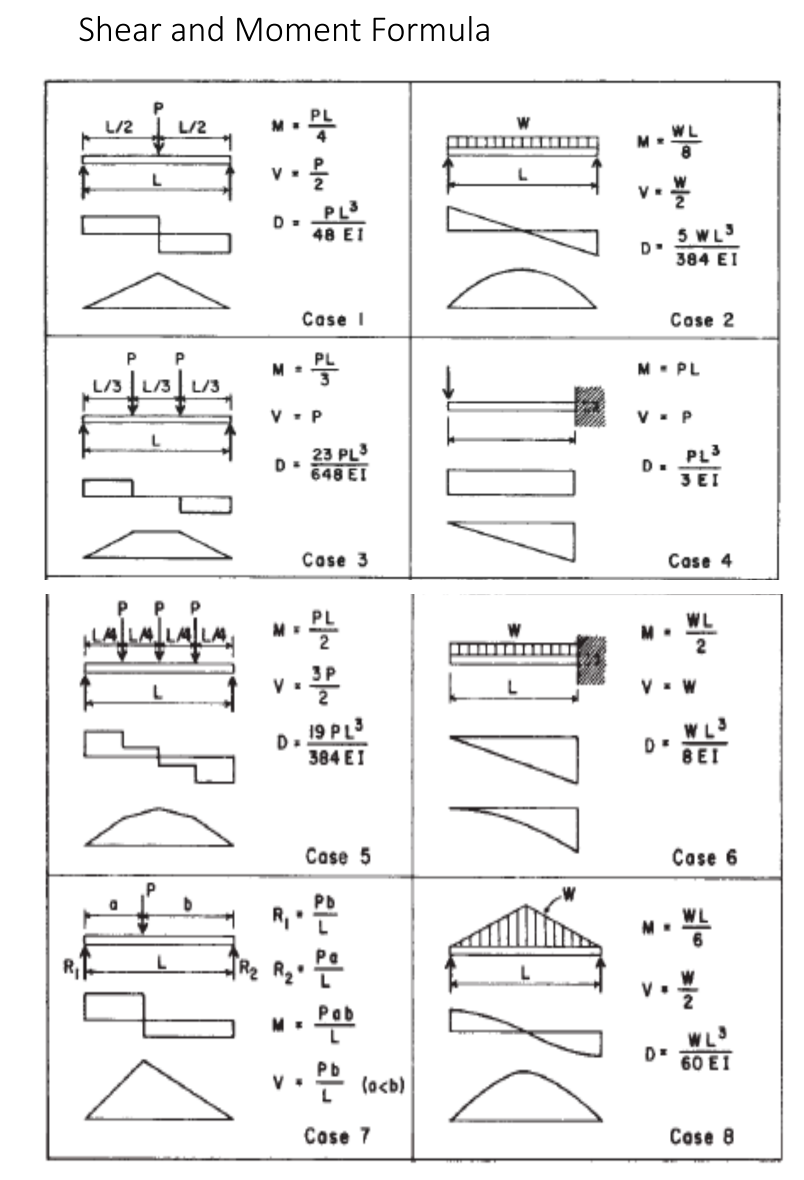
Derive the formula for the maximum shear and maximum bending moments for Case 1 to case 8.


Q: Find the Shear Moment Diagram of the following problems using
A:
Q: If the shape in problem 5 is used for a beam with Mmax = 25 k-ft, what is the maximum bending…
A:
Q: Find the shear force, internal axial force and bending moment at point C in the beam. Please include…
A: The free-body diagram of the given loading beam can be drawn as, Here, RAH is the horizontal…
Q: (a) For the beam and loading shown in Figure Q. 4a, draw the shear force and bending moment…
A: In the question we can find the shear force and bending moment diagram
Q: The shear diagram will jump downward if the _________________ a. Total weight is applied b.…
A: To Fill in the blank for the question where The shear diagram will jump downward Option given are…
Q: 新 A 5 -
A:
Q: (a) Make Free Body Diagram (b) Find all the reactions labelled (c) Find the internal Shear and…
A:
Q: derive shear and moment equations
A:
Q: Determine the MAXIMUM SHEAR and MAXIMUM MOMENTS for using SHEAR AND MOMENT DIAGRAMS OR BY ANALYTICAL…
A: We can solve first question since the exact one is not specified. Please resubmit the question by…
Q: What is the internal normal force, shear force, and bending moment at point C, if F=40kN?
A: Given The value of force is F=40 kN. The load on beam consist of uniform distributed, uniform…
Q: Write shear and moment equations for the beams in the following problems. In each problem, let x be…
A: The given beam is supported by a cantilever type. The support will exert horizontal component,…
Q: Draw bending moment diagram along with calculations and note the values on the diagram
A: Shear force diagram represents shear force at every section of the beam. Shear force at any…
Q: QUESTION 16 Calculate the Marin size factor k, for a non-rotating square beam loaded in fully…
A: Find the marin size factor.
Q: A) What is the axial force along AB? FAR = units B) What must be the minimum diameter of the pin at…
A: Given:P=200 lbFoS=2.5shear stress at failure for the pin material= 16 ksi
Q: A downward linearly distributed load and an upward linearly distributed load, both with intensity of…
A:
Q: moment diagram using differential relationship between loads, shear forces and bending moments
A: We must first calculate the reaction forces acting on the support points of the beam using the three…
Q: (a) Make Free Body Diagram (b) Find all the reactions labelled (c) Find the internal Shear and…
A: As per guidelines we need to answer only 1st three subparts
Q: Draw shear force and bending moment diagrams for the beam and loading in the figure.
A: Let HA and VA be the horizontally forward and vertically upward reaction at support A respectively…
Q: -) A hollow circular steel shaft has a 150 mm outer diameter, and a 100 mm inside diameter. The…
A:
Q: Derive the formula for the maximum shear and maximum bending moments for Case 1 to case 4
A:
Q: Describe the Torsional Moment?
A:
Q: Draw Shear and Moment Diagrams.
A: A pin support will exert both horizontal and vertical components of reaction. The supports given are…
Q: Derive the expression of shear plane angle. Draw and mention all corresponding angle required for…
A:
Q: Write shear and moment equations for the beams in the following problems. In each problem, let x be…
A: Draw the free-body diagram of the given beam. Apply force equilibrium in a horizontal direction.…
Q: Task 2: Determine expressions for the distributions of bending moment and shearing force for the…
A: The given beam is an overhanging beam. And to determine the shear force and bending moment first we…
Q: The cross-section of a rectangular beam 25 mm by 72 mm and is subjected to a combined loading of 65…
A:
Q: 3: Draw the N, M. T diagrams of the internal influence forces of the given beam for the following…
A:
Q: IN-CLASS EX. 5-6 • Draw the complete shearing force and bending moment diagrams for the beam. 800 N…
A:
Q: FIGURE PS-39 2.5 K/ft 2 ft 4ft 1. Compute the reactions at the supports using the tech- niques shown…
A:
Q: How can the Shear and moment diagrams be constructed?
A: Before drawing the shear force and bending moment diagrams let's know about their sign conventions.…
Q: strength of materials 1.) Derive the formula for the maximum shear and maximum bending moments for…
A:
Q: Derive the formula for the maximum shearing stress due to bending if the the cross section is a…
A: Derive the formula for the maximum shearing stress due to bending
Q: he lightest W-shape for the beam shown if the working stress in bending is 20 ksi. What is the…
A: ∑Mc=0By×16-2000×24-250×16×8+2000×8=0By=4000lb ∑Fy=0By+Cy-2000-2000-250×16=0Cy=4000lb…
Q: strength of materials Derive the formula for the maximum shear and maximum bending moments for Case…
A:
Q: solid circular shaft is subjected to a bending moment of 300 kNm, a twisting moment of 125 kNm. If…
A:
Q: Describe the Graphical method for constructing Shear and Moment Diagrams?
A: If the variation of V and M are written as functions of position, x, and plotted, the resulting…
Q: Derive an expression for an equivalent torque Te that, if applied alone to a solid bar with a…
A: Let us assume shaft is having diameter, d Case(a) shaft is subjected to M & T σbending=32Mπd3,…
Q: 40 lb/in. 9 in. FIGURE PS-39 1. Compute the reactions at the supports using the tech- niques shown…
A:
Q: A solid and a hollow shaft are made of same material. The diameter of the solid shaft is 300 mm and…
A:
Q: Question 4 A shaft of 75 mm diameter fails (experiences the onset of yield) under a bending moment…
A:
Q: Find Out Shear and moment equations
A:
Q: Sketch the graphs of the shear and bending- moment equations for the following situations, where the…
A: Given:
Q: d the shear and am shown in fig
A:
Q: Beam loaded as shown in Fig. find the shear force and bending moment equations and sketch shear and…
A:
Q: 14.2 In below configuration, if the I beam is W12X16, the distance from the root of column to the…
A: Solution : The moment is given as : For the given beam specification the section modulus is given…
Q: nish and heat-treated to a tensile strength of 110kpsi, loaded in rotating bending.
A:
Q: hese garden shears were manufactured using an inferior material. Using a loading of 50 lb applied…
A: Consider the cross section of the shear is square shape of aspects 50 mm x 20mm Assuming the length…
Q: Write the shear and moment equations and draw the shear and moment diagrams with step by each…
A: SF and BM Diagram of the above beam can be given as:
Derive the formula for the maximum shear and maximum bending
moments for Case 1 to case 8.


Trending now
This is a popular solution!

Step by step
Solved in 2 steps with 1 images

- Repeat Problem 11.2-3 assuming that R= 10 kN · m/rad and L = 2 m.4kN/m uniform spring load h = 2b allowable normal stress 12MPa h(min) = ?The following shaft is made of steel (Sut = 520 MPa, Se = 260 MPa) and is subjected to 3 loads at C; an axial load P, a bending force F, and a torque T. The shaft is fixed at its left end A. A fillet of 2 mm radius exists at B. The loads fluctuate such that Fmin = 0 and Fmax = 100 N, Pmin = 0 N and Pmax= 1000 N, and Tmin = 0 and Tmax = 100 N.m. For the shaft, find the factor of safety for infinite life (using Case 3 safety factor calculation) at B. Assume all fatigue stress concentration factors are equal to 1.
- Q.2 A hollow simple supported shaft 3m made of steel with di/do of 0.6. The shaft is subjected to a bending force of 4 KN and transmits 52 KW with 150 rpm. Find the outer and inner diameter of the shaft, if the ultimate shear stress of 600 MPa and allowable compression stress of 100 MPa, tack safety factor 7.Given: l1=2l; l2=1,2l; l3=1,5l; M1=-1,7M; M2=0M; M3=1,4M. Parameter of length l=40cm; parameter of load М=410Nm. The shaft is made of steel with yielding shear stress τY=190MPa; factor of safety n=1,9. Find: the diameter (in mm) of cross section from strength calculation d = ?Given: l1=1,3l; l2=1,9l; l3=1,2l; M1=-0,6M; M2=-1,6M; M3=1,9M. Parameter of length l=40cm; cross section diameters: d=41mm; d0=26mm. The shaft is made of steel with yielding shear stress τY=250MPa; factor of safety n=1,6. Find: the allowable value of load parameter (in Nm) MA = ?
- A 16 ft steel line shaft has no bending action except its own weight. What power in hp can shaft deliver at a speed of 200 rpm. Consider that the torsional deflection wm not exceed 0.08o/ft of length.The connecting rod of a four stroke cycle Diesel engineis of circular section and of length 550 mm. The diameter and stroke of the cylinder are 150 mm and240 mm respectively. The maximum combustion pressure is 4.7 N/mm2. Determine the diameter ofthe rod to be used, for a factor of safety of 3 with a material having a yield point of 330 MPa.Find also the maximum bending stress in the connecting rod due to whipping action if the engine runsat 1000 r.p.m. The specific weight of the material is 7800 kg/m3. [Ans. 33.2 mm ; 48 MPa]1.1. State three underlying assumptions in the formulation of the torsion formula, .TGJrl (3) 1.2 A hollow shaft has to be designed for a marine engine delivering 1200 kW when running at 120 r/min. The maximum allowable shear stress is 50 MPa and the maximum torque to be transmitted by the shaft is 30 % greater than the mean torque. The internal diameter of the shaft is 50 % that of the external diameter. Calculate: 1.2.1 The dimensions of the shaft and the angle of twist of the shaft over 3 m when transmitting the above torque (G = 80 GPa). (14) 1.3 Determine the torsional rigidity of a 300 mm long steel shaft with a diameter of 50 mm. (G = 80 GPa
- A turbine shaft transmits 500 kW power at 900 rpm. The permissible shear stress is 80N/mm² while twist is limited to 0.5º in a length of 2.5 m. Take G = 0.8x10⁵ N/mm², on thebasis of torsional rigidity;i.Determine diameter of shaft if solid shaft is used.ii.If hollow shaft is chosen with di/do = 0.6, determine the suitable diameters of theshaft. please write with ball pen.. thank youA solid circular shaft has a diameter of d mm and is made from steel, which fail when tested in simple tension test at a stress of 150 MPa. The shaft was subjected by bending moment and torque which are 22.2 kNm and 44.4 kNm respectively. Calculate the minimum allowable shaft diameter, d according to:- (a) Tresca failure criterion (b) Von Mises theory of elastic failurecampute the bending stress number for the goer pair described by the given data beLow. KS= 1, Km= 1,21, F= 2.00 in, DP= 3,33 in, NG= 70, Np=20 hp = 1750v. p.m, Av=11, Pd =6, Tp= 900ib V1= 1527 ft/min The matarial used for pinion a gear is cast iron