Design and draw a three-stage amplifier connected in series with gains of +15, -21, and -30 by using OPAMPS. Use a 420 kN feedback resistor for all stages. What output voltage results for an input of V, = 2 mV? %3D
Q: (а) There are three voltage inputs of V1= lv, V2= 3v and V3 = 4v, and three resistors with %3D the…
A: An OPAMP(operational amplifier) is an integrated electronic circuit that is used to amplify weak…
Q: 9. If the upper critical frequency of a low frequency amplifier is 200 Hz, its bandwidth is: a) O…
A: Low frequency amplifier is also known as low pass filter means which allows frequency component…
Q: Design an inverting summing amplifier using a 120 kohm resistor in the feedback path so that vo=…
A:
Q: Q2 a- Draw a circuit diagram of a 311 op-amp showing an input of 10 V rms with f= 1KHZ, applied to…
A: 311 is a Differential Comparator (A s per datasheet) in which when Non Inverting voltage is…
Q: 1. Design an inverting-summing amplifier using a 120 kΩ resistor in the feedback path so that…
A: Since you have asked multiple question, we will solve the first question for you. If you want any…
Q: H.W. 2: Design an inverting op-amp circuit for which the gain is -10 and the to resistance used is…
A:
Q: 4. (a). (b). Operational amplifiers (op-amps) are used in integrated circuits for signal…
A: Given a circuit of an operational amplifier as shown below. Find State characteristic of the ideal…
Q: A one-pole amplifier offers a voltage gain of 10,000 (A=10,000) and a 3-dB cut-off frequency of 100…
A:
Q: basic electronics please give full answer thanks Compare inverting and non-inverting amplifier.…
A: 1)In inverting opamp It provides an amplified signal which is out of phase with the applied input.…
Q: Problem 1. (P1) Three op-amps are connected in cascade configuration. An 80 microVolts signal is…
A: In this question , cascaded configuration of opamp is given...We have to find out gain of 3rd…
Q: If an opamp is performing by keeping two input voltages as 40mV and 80mV at inverting and non…
A: Given : V1= 40 mV V2= 80mV V0=200mV Ri=20 ohm Feedback Resitsance = 60 ohm
Q: ov- -5V- V(vo1) 12V- ov -12V V(v2) V(vnoise) 5V- -5V- V(vo2) 12V
A: Due to the presence of noise as it can be seen from the simulation diagram given the output v01,…
Q: Design a unity gain inverting summing amplifier that will output the sum of two input voltages. Use…
A:
Q: Q2 Re 2.2 k Re For the series-series feedback amplifier in right figure, find the value of Rg, The…
A:
Q: As, we have learned during the lectures that an op amp combined with a balanced resistance bridge…
A: We know, that an operational amplifier combined with a balanced resistance bridge helps the circuit…
Q: 1. Consider the amplifier circuit shown below. Assuming that the amplifier block is an ideal op-…
A:
Q: PASSAGE If an opamp is perfroming by keeping two input voltages as 40 mV and 80 ml at inverting…
A: The circuit diagram can be drawn as
Q: A noninverting amplifier is built with R2 = 75 kΩ and R1 = 5.6kΩ using an op amp with an open -loop…
A: Given: R1=5.6 kΩR2=75 kΩA=100 dB Input Resistance= 500 kΩ Output Resistance= 300 Ω
Q: Assuming that the op-amps are ideal, what is the nodal voltage Vo1, Vo2, and Vout, respectively?…
A: In the Op-Amp : Voltage at inverting terminal= voltage at non inverting terminal i.e, V-=V+ […
Q: An inverting amplifier is to be designed to have a closed-loop gain of 60 dB. The only op amp that is…
A: Given Closed loop gain in dB AV=60 dB Open loop gain in dB A=106 dB FGE≤1 percent…
Q: The above op-amp acts in a non ideal manner such that R₂ R₁ Av(CL) = 1 1+ Av(OL) 1+R²₁. Given Av(OL)…
A: Given: AVCL=-R2R11+1AVOL1+R2R1
Q: A non-inverting op-amp circuit has the open loop gain of 136 and the resistances R1=3500 Ω and R2 =…
A:
Q: 2. A circuit containing a non-ideal op-amp is shown below. For your reference, the model for a…
A:
Q: Design a circuit using op amps, to perform the following operation: vo = 4va + 5vB – vc Now, choose…
A: The output of the circuit formed by the op-amps is, vO=4vA+5vB-vC The circuit is,
Q: w the connection of three combination op-amp stages ( Parallel and series connection) using an LM348…
A: Gain of 1st stage is +110.Which means, op-amp in 1st stage must be non-inverting amplifier. Given:…
Q: For the circuit shown, • R = 22 kN R2 • R2 = 180 k2 R, The op-amp is ideal. Determine the…
A:
Q: A single-pole op amp has an open-loop gain of 95 dB and a unity-gain frequency of 2 MHz. (a) The op…
A: Given f=2 MHz Calculating angular frequency ωT=2πfωT=2π2 MHzωT=4×10⁶ π
Q: 3A Problem 1. (P1) Three op-amps are connected in cascade configuration. An 80 microVolts signal is…
A: Note : Please note that all the given options are incorrect by solving in simplified manner we have…
Q: Figure Q3 is an ideal Operational Amplifier circuit. a) What is the voltage Vị at the negative side…
A: This question belongs to analog electronics. It is based on the properties of ideal operational…
Q: For ideal op amp operating with the following feedback network in the non-inverting configuration,…
A: Non-Inverting Opamp gain is given by A= 1+(R2/R1) and that of inverting opamp has gain = (-R2/R1)…
Q: A single-pole op amp has an open-loop gain of 86dB and a unity-gain frequency of 5MHz . What is the…
A: Concept: The small signal amplifier is generally referred to as a voltage amplifier because they are…
Q: The above op-amp acts in a non ideal manner such that R₂ R₁ Av(CL) = - 1 1+ AV(OL) (1+1) Given…
A: Given: AVOL=104 and AVCL=-R2R11+1AVOL1+R2R1
Q: Resistance B. Zero Ohm Output Resistance C. Input terminals do not let current to flow D.…
A:
Q: 4.2 An op amp with an open-loop gain of 6 × 10° and Vec = 10 V has an output voltage of 3 V. If the…
A:
Q: 5. What should be the value of the input voltage applied to a non-inverting amplifier to produce an…
A: Given: In a non-inverting amplifier V0=5 VRf=5000 ΩRin=2000 Ω
Q: 3G Problem 1. (P1) Three op-amps are connected in cascade configuration. An 80 microVolts signal is…
A:
Q: 5. Design a circuit using two op amps, to perform the following operation: vo = vị + v2 – 2v3 Now,…
A: We need to design the circuit for given output
Q: A noninverting amplifier is built with R2 = 47 kΩ and R1 = 6.2k Ω using an op amp with an open-loop…
A: According to question: Closed loop gain of non inverting amplifier is…
Q: Some of the exercises show op-amps with a positive supply voltage but no information about negative…
A: The given circuit is shown below, after marking nodes
Q: A noninverting amplifier is built with 0.01 percent precision resistors and designed with R2 = 99R1.…
A: For an ideal op-amp, the voltage gain is, Av=1+R2R1 The nominal value of voltage gain is given by…
Q: Determine the CMRR and express it in dB for an op-amp with an open-loop differential voltage gain of…
A: Given : Note : What is the kind notice that according to the guidelines of the company if the…
Q: A positive-feedback amplifier circuit (inverting Schmitt trigger) shown in the following figure…
A: Here we have positive feedback so this amplifier works as an comparator. If non inverting terminal…
Q: f an opamp is perfroming by keeping two input voltages as 40 mV and 80 ml at inverting and non…
A: The circuit diagram can be drawn
Q: for the Operational Amplifier shown below, given that the input signal is a sine wave, if the…
A: The solution is given below
Q: 5. For an op-amp having a slew rate of SR = 2.4 V/us, what is the maximum closed-loop voltage gain…
A: Given Slew Rate = 2.4 And input signal varies by 0.3 V in 10 micro seconds. Then find the maximum…
Q: Design a unity gain inverting summing amplifier that will output the sum of two input voltages. Use…
A:
Q: For an input of V1 = 100 mV in an inverting amplifier whose closed-loop voltage gain is 40,…
A:
Q: For ideal op amps operating with the following feedback networks in the inverting configuration,…
A: Given, Here R1=50 kΩR2=100 kΩ
Can you aolve this question as fast as possible please
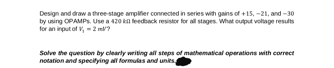
Step by step
Solved in 5 steps with 3 images
- Find out the gain of inverting amplifier if it is performing on 12 V supply, it has input resistance of 20 ohm and feedback resistance of 50 ohm respectively. NOTE : KINDLY ELABORATE BRIEFLYQuestion 2 Part (A) Design an inverting amplifier with a gain of 4. Use an ideal ops amp, a 30kΩ resistorin the feedback path, and ±12V power supplies. Part (B) Using your design from part (a), determine the range of input voltages that will keepthe op amp in the linear operating regions. Part (C) Suppose you wish to amplify a 2V signal, using your design from part (a) with avariable feedback resistor. What is the largest value for the feedback resistance thatkeeps the op amp in the linear operating region? Using this resistance value, what isthe new gain of the inverting amplifier.A certain op-amp is used in a feedback configuration having a gain of 20 and a bandwidth of 500 kHz. a)If the external resistor values are changed to increase the gain to 40, what is the new bandwidth? The new bandwidth is 250khz What is the unity-gain bandwidth of the op-amp ??
- a) Design an inverting amplifier with a gain of 4. Use an ideal op amp, a 30 kohm resistor in the feedback path, and +-12 v power supplies. b) Using your design from part a, determine the range of input voltages that will keep the op amp in it's linear operating region. c) suppose you wish to amplify a 2 V signal, using your design from part a, with a variable feedback resistor. What is the largest value of feedback resistance that keeps the op amp in its linear operation region? Using this resistor value, what is the new gain of the inverting amplifier?1. Design an inverting amplifier with a gain of 4. Use an ideal op amp, a 30 kΩ resistor in the feedback path, and ±12 V power supplies. 2. Using your design from part (a), determine the range of input voltages that will keep the op amp in its linear operating region. 3. Suppose you wish to amplify a 2 V signal, using your design from part (a) with a variable feedback resistor. What is the largest value of feedback resistance that keeps the op amp in its linear operation region? Using this resistor value, what is the new gain of the inverting amplifier?Assume an operational amplifier is working on inverting amplifier in which it takes input resistance and feedback resistance of 30ohm and 60ohm respectively.If input voltage is applied at 150 volt then examine following parameters. Evaluate the gain of opamp if input voltage is applied on non-inverting amplifier. Options: A)4 B)3 C)2 D)5
- Assume an operational amplifier is working on inverting amplifer in which it takes input resistance and feedback resistance of 30 ohm and 60 ohm respectively. If input voltage is applied at 150 volt then examine following parameters1.Evaluate over gain of amplifier2.Evaluate the gain of opamp if input voltage is applied on non inverting amplifier3.Calculate output voltage of amplifier4.If input voltage is changed from inverting terminal to non inverting terminal then calculate its output voltage5. If we add one more input resistance of 40 ohm at inverting terminal at 20 voit input supply voltage and working as adder then calculate the output voltage.Discuss the effect of changing the value of the feedback resistor on the output voltage. What is the polarity relationship between the input and the output of the inverting amplifier? Discuss how you control the gain of the amplifier? From the results of part 2, discuss the effect of changing the frequency of the input signal. Give possible applications for this amplifier. Add any comments you think necessary based on the observationsFind the closed-loop transconductance, input resistance, and output resistance for the series-series feedback amplifier as shown if the op amp has an open-loop gain of 80 dB, an input resistance of 25kΩ , and an output resistance of 1kΩ. Assume the amplifier is driven by a signal voltage with a 10-kΩ source resistance, and the feedback network is implemented with R2=91kΩ and R1=10kΩ.
- Consider the following statement: In feedback amplifiers, concerning the connections between the direct amplifiers and the feedbacks network, a shunt connectiın at the input part servers to set an increased versiın of the input impedance of the direct amplifier, whereas again a shunt connection at the output part services to set a decreased version of the output imdepance of direct amplifier. Explain what is wrong with the statement above by drawing representative circuit diagrams and outlining the necessary calculations.Find the gain of non inverting amplifier if it has input voltage is 5V, input resistance of 20 ohm and feedback resistance of 40 ohm. NOTE : KINDLY ELABORATE BRIEFLY2. Design a unity gain inverting summing amplifier that will output the sum of two input voltages. Use a feedback resistor of 2.5 Kohms.