Determine the bending moment acting at each of the following locations: (a)x= 10.5 ft (i.e., at support B) (b)x= 31.5 ft
Determine the bending moment acting at each of the following locations: (a)x= 10.5 ft (i.e., at support B) (b)x= 31.5 ft

International Edition---engineering Mechanics: Statics, 4th Edition
4th Edition
ISBN:9781305501607
Author:Andrew Pytel And Jaan Kiusalaas
Publisher:Andrew Pytel And Jaan Kiusalaas
Chapter6: Beams And Cables
Section: Chapter Questions
Problem 6.42P: For the beam AB shown in Cases 1 and 2, derive and plot expressions for the shear force and bending...

Related questions

Question
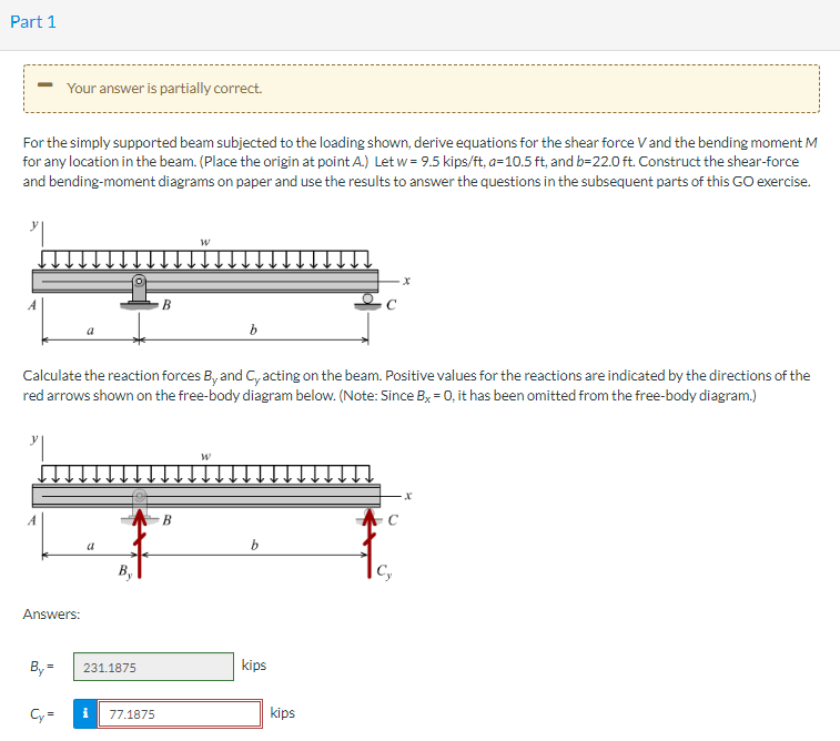
Transcribed Image Text:Part 1
For the simply supported beam subjected to the loading shown, derive equations for the shear force V and the bending moment M
for any location in the beam. (Place the origin at point A.) Let w = 9.5 kips/ft, a=10.5 ft, and b=22.0 ft. Construct the shear-force
and bending-moment diagrams on paper and use the results to answer the questions in the subsequent parts of this GO exercise.
Your answer is partially correct.
Answers:
By=
Cy=
Calculate the reaction forces By and C, acting on the beam. Positive values for the reactions are indicated by the directions of the
red arrows shown on the free-body diagram below. (Note: Since Bx = 0, it has been omitted from the free-body diagram.)
a
231.1875
B
i 77.1875
W
B
b
W
b
kips
kips
Cy
X
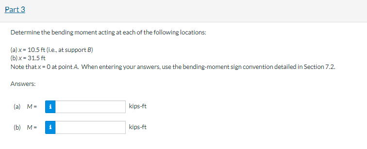
Transcribed Image Text:Part 3
Determine the bending moment acting at each of the following locations:
(a) x = 10.5 ft (i.e., at support B)
(b)x= 31.5 ft
Note that x = 0 at point A. When entering your answers, use the bending-moment sign convention detailed in Section 7.2.
Answers:
(a) M= i
(b) M= i
kips-ft
kips-ft
Expert Solution
This question has been solved!
Explore an expertly crafted, step-by-step solution for a thorough understanding of key concepts.

Step by step
Solved in 4 steps with 4 images

Knowledge Booster


Learn more about
Need a deep-dive on the concept behind this application? Look no further. Learn more about this topic, mechanical-engineering and related others by exploring similar questions and additional content below.Recommended textbooks for you
International Edition---engineering Mechanics: St…
Mechanical Engineering
ISBN:
9781305501607
Author:
Andrew Pytel And Jaan Kiusalaas
Publisher:
CENGAGE L
International Edition---engineering Mechanics: St…
Mechanical Engineering
ISBN:
9781305501607
Author:
Andrew Pytel And Jaan Kiusalaas
Publisher:
CENGAGE L