For the simply supported beam subjected to the loading shown, derive equations for the shear force V and the bending moment M for any location in the beam. (Place the origin at point A.) Let a=2.50 m, b=4.25 m, Pg= 45kN, and Pc = 90kN. Construct the shear- force and bending-moment diagrams on paper and use the results to answer the questions in the subsequent parts of this GO exercise.
For the simply supported beam subjected to the loading shown, derive equations for the shear force V and the bending moment M for any location in the beam. (Place the origin at point A.) Let a=2.50 m, b=4.25 m, Pg= 45kN, and Pc = 90kN. Construct the shear- force and bending-moment diagrams on paper and use the results to answer the questions in the subsequent parts of this GO exercise.

Elements Of Electromagnetics
7th Edition
ISBN:9780190698614
Author:Sadiku, Matthew N. O.
Publisher:Sadiku, Matthew N. O.
ChapterMA: Math Assessment
Section: Chapter Questions
Problem 1.1MA

Related questions

Question
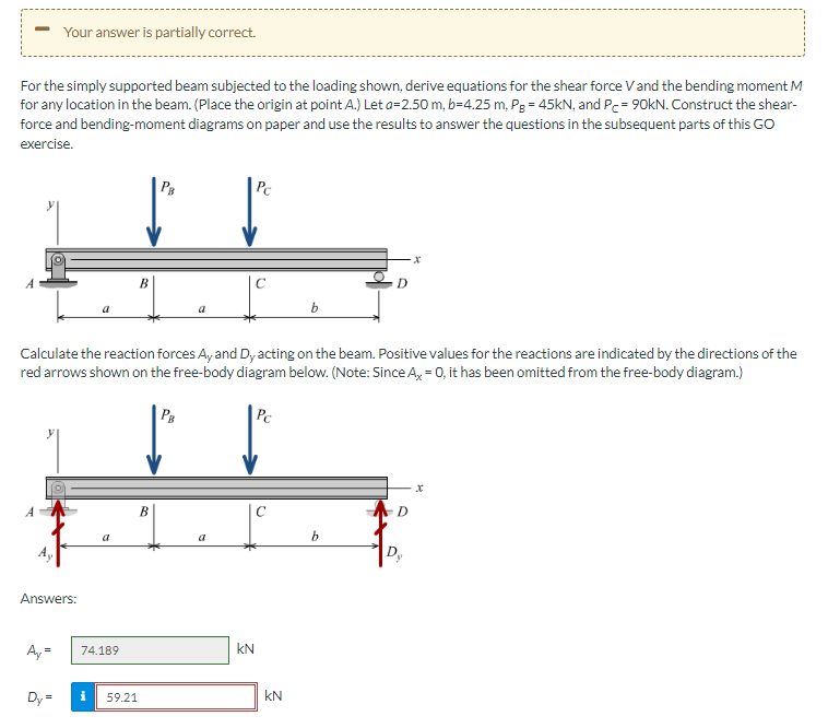
Transcribed Image Text:Your answer is partially correct.
For the simply supported beam subjected to the loading shown, derive equations for the shear force V and the bending moment M
for any location in the beam. (Place the origin at point A.) Let a=2.50 m, b=4.25 m, Pg= 45kN, and Pc = 90kN. Construct the shear-
force and bending-moment diagrams on paper and use the results to answer the questions in the subsequent parts of this GO
exercise.
Answers:
a
B
Ay=
Dy= i 59.21
74.189
Calculate the reaction forces Ay and Dy acting on the beam. Positive values for the reactions are indicated by the directions of the
red arrows shown on the free-body diagram below. (Note: Since Ax = 0, it has been omitted from the free-body diagram.)
B
a
PB
a
Pc
KN
Pc
b
KN
D
b
D
P
x
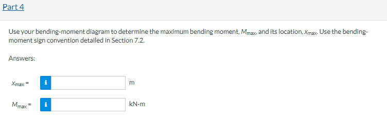
Transcribed Image Text:Part 4
Use your bending-moment diagram to determine the maximum bending moment, Mmax, and its location, Xmax. Use the bending-
moment sign convention detailed in Section 7.2.
Answers:
Xmax =
Mmax
=
i
i
m
kN-m
Expert Solution
This question has been solved!
Explore an expertly crafted, step-by-step solution for a thorough understanding of key concepts.

Step by step
Solved in 3 steps with 3 images

Knowledge Booster


Learn more about
Need a deep-dive on the concept behind this application? Look no further. Learn more about this topic, mechanical-engineering and related others by exploring similar questions and additional content below.Recommended textbooks for you
Elements Of Electromagnetics
Mechanical Engineering
ISBN:
9780190698614
Author:
Sadiku, Matthew N. O.
Publisher:
Oxford University Press

Mechanics of Materials (10th Edition)
Mechanical Engineering
ISBN:
9780134319650
Author:
Russell C. Hibbeler
Publisher:
PEARSON

Thermodynamics: An Engineering Approach
Mechanical Engineering
ISBN:
9781259822674
Author:
Yunus A. Cengel Dr., Michael A. Boles
Publisher:
McGraw-Hill Education
Elements Of Electromagnetics
Mechanical Engineering
ISBN:
9780190698614
Author:
Sadiku, Matthew N. O.
Publisher:
Oxford University Press
Mechanics of Materials (10th Edition)
Mechanical Engineering
ISBN:
9780134319650
Author:
Russell C. Hibbeler
Publisher:
PEARSON
Thermodynamics: An Engineering Approach
Mechanical Engineering
ISBN:
9781259822674
Author:
Yunus A. Cengel Dr., Michael A. Boles
Publisher:
McGraw-Hill Education

Control Systems Engineering
Mechanical Engineering
ISBN:
9781118170519
Author:
Norman S. Nise
Publisher:
WILEY

Mechanics of Materials (MindTap Course List)
Mechanical Engineering
ISBN:
9781337093347
Author:
Barry J. Goodno, James M. Gere
Publisher:
Cengage Learning

Engineering Mechanics: Statics
Mechanical Engineering
ISBN:
9781118807330
Author:
James L. Meriam, L. G. Kraige, J. N. Bolton
Publisher:
WILEY