Determine the resultant moment about point A of the system of forces shown in figure below. Each square is 1 ft. on a side. 80 lb 80 lb 100 Ib 100 lb 100 1b
Determine the resultant moment about point A of the system of forces shown in figure below. Each square is 1 ft. on a side. 80 lb 80 lb 100 Ib 100 lb 100 1b

Chapter2: Loads On Structures
Section: Chapter Questions
Problem 1P

Related questions
Question
100%
1.)Given and requirement(s)
2.)Free body diagram
3.) Formulas and its proper symbols
4.) Direction of forces and sign convention.
The vertical and horizontal components must also be indicated in your free body diagram. Use three significant figures for your final answer and box it.
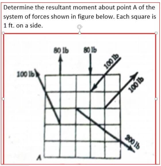
Transcribed Image Text:system of forces shown in figure below. Each square is
1 ft. on a side.
Determine the resultant moment about point A of the
80 lb
80 lb
100 Ib
200 lb
100 lb
100 b
Expert Solution
This question has been solved!
Explore an expertly crafted, step-by-step solution for a thorough understanding of key concepts.

Step by step
Solved in 3 steps with 3 images

Knowledge Booster


Learn more about
Need a deep-dive on the concept behind this application? Look no further. Learn more about this topic, civil-engineering and related others by exploring similar questions and additional content below.Recommended textbooks for you

Structural Analysis (10th Edition)
Civil Engineering
ISBN:
9780134610672
Author:
Russell C. Hibbeler
Publisher:
PEARSON

Principles of Foundation Engineering (MindTap Cou…
Civil Engineering
ISBN:
9781337705028
Author:
Braja M. Das, Nagaratnam Sivakugan
Publisher:
Cengage Learning
Structural Analysis (10th Edition)
Civil Engineering
ISBN:
9780134610672
Author:
Russell C. Hibbeler
Publisher:
PEARSON
Principles of Foundation Engineering (MindTap Cou…
Civil Engineering
ISBN:
9781337705028
Author:
Braja M. Das, Nagaratnam Sivakugan
Publisher:
Cengage Learning

Fundamentals of Structural Analysis
Civil Engineering
ISBN:
9780073398006
Author:
Kenneth M. Leet Emeritus, Chia-Ming Uang, Joel Lanning
Publisher:
McGraw-Hill Education


Traffic and Highway Engineering
Civil Engineering
ISBN:
9781305156241
Author:
Garber, Nicholas J.
Publisher:
Cengage Learning