DI 9:2 V = 240 Vrms AC f= 60 Hz R: B Figure QB.I A rectifier circuit Referring to the half-wave rectifier circuit in Figure QB.1, diode D; is made of Silicon with Vp 0.7 (i) Draw and label the voltage waveforms Vpri and Vec for two complete cycles on the same axis. (ii) Draw and label the voltage waveform of Vpi and then determine the peak inverse voltage, PIV of diode DI. (iii) Calculate the value of Vopeak) during positive cycle and negative cycle of Vsee.
DI 9:2 V = 240 Vrms AC f= 60 Hz R: B Figure QB.I A rectifier circuit Referring to the half-wave rectifier circuit in Figure QB.1, diode D; is made of Silicon with Vp 0.7 (i) Draw and label the voltage waveforms Vpri and Vec for two complete cycles on the same axis. (ii) Draw and label the voltage waveform of Vpi and then determine the peak inverse voltage, PIV of diode DI. (iii) Calculate the value of Vopeak) during positive cycle and negative cycle of Vsee.

Power System Analysis and Design (MindTap Course List)
6th Edition
ISBN:9781305632134
Author:J. Duncan Glover, Thomas Overbye, Mulukutla S. Sarma
Publisher:J. Duncan Glover, Thomas Overbye, Mulukutla S. Sarma
Chapter4: Transmission Line Parameters
Section: Chapter Questions
Problem 4.2P: The temperature dependence of resistance is also quantified by the relation R2=R1[ 1+(T2T1) ] where...

Related questions
Question
Transcribed Image Text:+ Vor -
9:2
D,
V = 240 Vm
AC
f= 60 Hz
R1
B
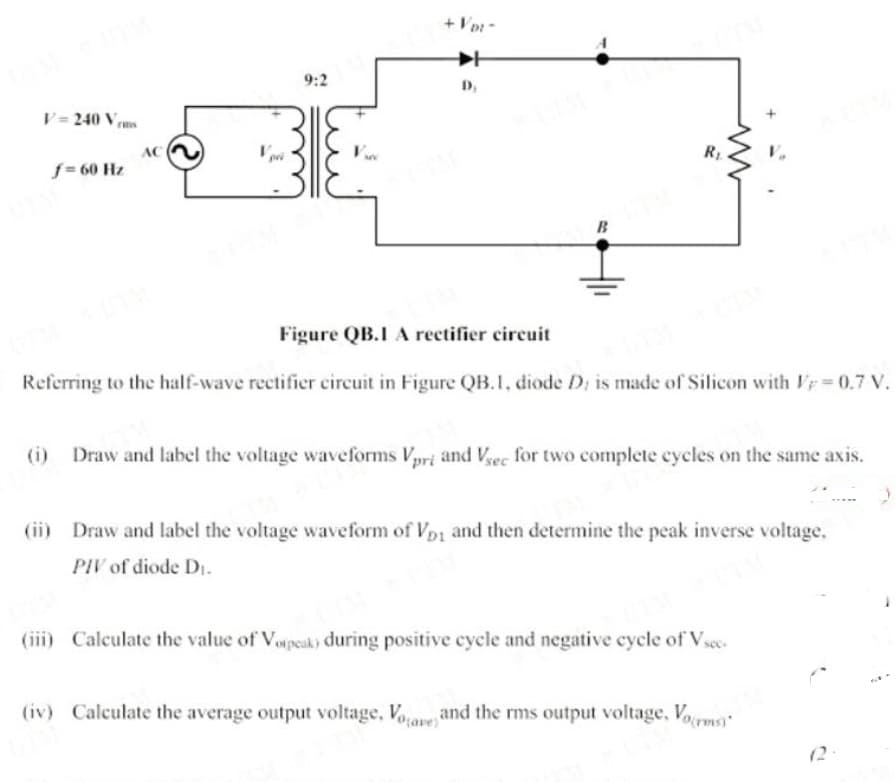
Figure QB.I A rectifier circuit
Referring to the half-wave rectifier circuit in Figure QB.1, diode D; is made of Silicon with Ir = 0.7 V.
(i) Draw and label the voltage waveforms Vpri and Vec for two complete cycles on the same axis.
(ii) Draw and label the voltage waveform of Vpi and then determine the peak inverse voltage,
PIV of diode DI.
(iii) Calculate the value of Vopeak) during positive cycle and negative cycle of Vsee.
(iv) Calculate the average output voltage, Voave and the rms output voltage, Vorms
(2
Expert Solution
This question has been solved!
Explore an expertly crafted, step-by-step solution for a thorough understanding of key concepts.

Step by step
Solved in 4 steps with 3 images

Knowledge Booster


Learn more about
Need a deep-dive on the concept behind this application? Look no further. Learn more about this topic, electrical-engineering and related others by exploring similar questions and additional content below.Recommended textbooks for you
Power System Analysis and Design (MindTap Course …
Electrical Engineering
ISBN:
9781305632134
Author:
J. Duncan Glover, Thomas Overbye, Mulukutla S. Sarma
Publisher:
Cengage Learning

Delmar's Standard Textbook Of Electricity
Electrical Engineering
ISBN:
9781337900348
Author:
Stephen L. Herman
Publisher:
Cengage Learning
Power System Analysis and Design (MindTap Course …
Electrical Engineering
ISBN:
9781305632134
Author:
J. Duncan Glover, Thomas Overbye, Mulukutla S. Sarma
Publisher:
Cengage Learning
Delmar's Standard Textbook Of Electricity
Electrical Engineering
ISBN:
9781337900348
Author:
Stephen L. Herman
Publisher:
Cengage Learning