draw a block diagram representing the QUBE-Servo 2 system indicating all the variables, signals, and the control system components.
draw a block diagram representing the QUBE-Servo 2 system indicating all the variables, signals, and the control system components.

Chapter40: Push-button Synchronizing
Section: Chapter Questions
Problem 5SQ

Related questions
Question
Identification of the physical system components and system integration: draw a
block diagram representing the QUBE-Servo 2 system indicating all the variables, signals,
and the control system components.
Please could you show what the in detail block diaagrams are given that the input and output of the servocontrol system are:
• input: voltage of the motor in V;
• output: inertia disk angular position in rad.
Transcribed Image Text:INNOVATE-EDUCATE
QUBE-Servo 2
ROTARY SERVO EXPERIMENT
www.BUANSER.COM
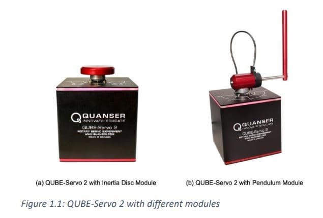
(a) QUBE-Servo 2 with Inertia Disc Module
QUANSER
INNOVATE EQUILLATE
QUBE
-Servo 2
Figure 1.1: QUBE-Servo 2 with different modules
NART
BAR
SEPER
-
J
(b) QUBE-Servo 2 with Pendulum Module
Expert Solution
This question has been solved!
Explore an expertly crafted, step-by-step solution for a thorough understanding of key concepts.

Step by step
Solved in 4 steps with 1 images

Knowledge Booster


Learn more about
Need a deep-dive on the concept behind this application? Look no further. Learn more about this topic, electrical-engineering and related others by exploring similar questions and additional content below.Recommended textbooks for you