
Introductory Circuit Analysis (13th Edition)
13th Edition
ISBN: 9780133923605
Author: Robert L. Boylestad
Publisher: PEARSON
expand_more
expand_more
format_list_bulleted
Related questions
Question
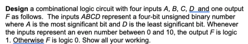

Transcribed Image Text:Design a combinational logic circuit with four inputs A, B, C, D and one output
F as follows. The inputs ABCD represent a four-bit unsigned binary number
where A is the most significant bit and D is the least significant bit. Whenever
the inputs represent an even number between 0 and 10, the output F is logic
1. Otherwise F is logic 0. Show all your working.
Expert Solution
This question has been solved!
Explore an expertly crafted, step-by-step solution for a thorough understanding of key concepts.

Step by stepSolved in 3 steps with 2 images

Knowledge Booster


Learn more about
Need a deep-dive on the concept behind this application? Look no further. Learn more about this topic, electrical-engineering and related others by exploring similar questions and additional content below.Similar questions
- Given the following logic function: F = x’y’z’ + xyz + xy’z + x’yz’ Draw the logic diagram after simplification. Verify the logic using Logisim.arrow_forwardA state machine produces consecutive outputs, at each rising edge of the clock, in the following sequence. A B 1 1 0 1 then repeating 0 0 etc The state transition logic in this system may be implemented by the logic circuit shown below. This circuit is designed using two D flip-flops as well as two logic gates referred to as i and ii in the figure below. ii 1D C1 B 1D C1 CLK a) What is the function of gate i? Please select your answer among the choices given below. Recall that a NOR-EXCLUSIVE gate is an OR-EXCLUSIVE gate with an inverted output, i.e. an OR-EXCLUSIVE gate followed by a NOT gate. O NOR-EXCLUSIVE O NAND O NOR Submit part Unanswered b) What is the function of gate ii? Please select your answer among the choices given below. O NAND O NOR-EXCLUSIVE O NOR Submit part Unansweredarrow_forwardRebuild the following logic circuits with the minimum possible number of logic gates and under the following conditions: Use only the AND and OR gates with 2-inputs. You can also use any number of NOT gates. f2=abc+abd+a'cd+b'cdarrow_forward
- a) Using two-level logic b) Using three-level logicarrow_forward1. Design a combinational logic circuit with three inputs A, B and C and one output X. When only one input is 1, output is 1. When none of input is 1, output is also 1. Otherwise, output is 0.arrow_forwardQ2. A sequential circuit has two D flip-flops, two inputs x and y, and one output z. the flip-flop input equations and the circuit output are as follows: D₁ = xy + xA, DB=B+xA, z = B a. Draw the logic diagram of the circuit b.Tabulate the state tablearrow_forward
- The waveforms are correct for the logic circuit shown. ADC D X A B C O True O False Xarrow_forwardDesign a logic circuit that illustrates Rule 11 of Boolean algebra: A+ AB = A + B A pulse generator is used to represent the input A and a switch is used for the input B. Switch B is open for B = 1 and closed for B = 0. Draw the logic circuit. Also, draw the timing diagrams for the following scenarios: i. B = 0 ii. B = 1arrow_forwardi will give you thumbs uparrow_forward
arrow_back_ios
arrow_forward_ios
Recommended textbooks for you
- Introductory Circuit Analysis (13th Edition)Electrical EngineeringISBN:9780133923605Author:Robert L. BoylestadPublisher:PEARSON
 Delmar's Standard Textbook Of ElectricityElectrical EngineeringISBN:9781337900348Author:Stephen L. HermanPublisher:Cengage Learning
 Programmable Logic ControllersElectrical EngineeringISBN:9780073373843Author:Frank D. PetruzellaPublisher:McGraw-Hill Education
  Fundamentals of Electric CircuitsElectrical EngineeringISBN:9780078028229Author:Charles K Alexander, Matthew SadikuPublisher:McGraw-Hill Education
 Electric Circuits. (11th Edition)Electrical EngineeringISBN:9780134746968Author:James W. Nilsson, Susan RiedelPublisher:PEARSON
 Engineering ElectromagneticsElectrical EngineeringISBN:9780078028151Author:Hayt, William H. (william Hart), Jr, BUCK, John A.Publisher:Mcgraw-hill Education,
Introductory Circuit Analysis (13th Edition)
Electrical Engineering
ISBN:9780133923605
Author:Robert L. Boylestad
Publisher:PEARSON
Delmar's Standard Textbook Of Electricity
Electrical Engineering
ISBN:9781337900348
Author:Stephen L. Herman
Publisher:Cengage Learning
Programmable Logic Controllers
Electrical Engineering
ISBN:9780073373843
Author:Frank D. Petruzella
Publisher:McGraw-Hill Education
Fundamentals of Electric Circuits
Electrical Engineering
ISBN:9780078028229
Author:Charles K Alexander, Matthew Sadiku
Publisher:McGraw-Hill Education
Electric Circuits. (11th Edition)
Electrical Engineering
ISBN:9780134746968
Author:James W. Nilsson, Susan Riedel
Publisher:PEARSON
Engineering Electromagnetics
Electrical Engineering
ISBN:9780078028151
Author:Hayt, William H. (william Hart), Jr, BUCK, John A.
Publisher:Mcgraw-hill Education,