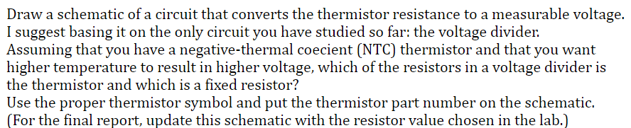
Draw a schematic of a circuit that converts the thermistor resistance to a measurable voltage. I suggest basing it on the only circuit you have studied so far: the voltage divider. Assuming that you have a negative-thermal coecient (NTC) thermistor and that you want higher temperature to result in higher voltage, which of the resistors in a voltage divider is the thermistor and which is a fixed resistor? Use the proper thermistor symbol and put the thermistor part number on the schematic. (For the final report, update this schematic with the resistor value chosen in the lab.)
Draw a schematic of a circuit that converts the thermistor resistance to a measurable voltage. I suggest basing it on the only circuit you have studied so far: the voltage divider. Assuming that you have a negative-thermal coecient (NTC) thermistor and that you want higher temperature to result in higher voltage, which of the resistors in a voltage divider is the thermistor and which is a fixed resistor? Use the proper thermistor symbol and put the thermistor part number on the schematic. (For the final report, update this schematic with the resistor value chosen in the lab.)

Delmar's Standard Textbook Of Electricity
7th Edition
ISBN:9781337900348
Author:Stephen L. Herman
Publisher:Stephen L. Herman
Chapter17: Resistive-inductive Series Circuits
Section: Chapter Questions
Problem 1PA: An AC electric motor is connected to a 240-V, 60-Hz source. A clamp-on ammeter with a peak hold...

Related questions
Question
Transcribed Image Text:Draw a schematic of a circuit that converts the thermistor resistance to a measurable voltage.
I suggest basing it on the only circuit you have studied so far: the voltage divider.
Assuming that you have a negative-thermal coecient (NTC) thermistor and that you want
higher temperature to result in higher voltage, which of the resistors in a voltage divider is
the thermistor and which is a fixed resistor?
Use the proper thermistor symbol and put the thermistor part number on the schematic.
(For the final report, update this schematic with the resistor value chosen in the lab.)
Expert Solution
This question has been solved!
Explore an expertly crafted, step-by-step solution for a thorough understanding of key concepts.

Step by step
Solved in 2 steps with 2 images

Recommended textbooks for you
Delmar's Standard Textbook Of Electricity
Electrical Engineering
ISBN:
9781337900348
Author:
Stephen L. Herman
Publisher:
Cengage Learning
Delmar's Standard Textbook Of Electricity
Electrical Engineering
ISBN:
9781337900348
Author:
Stephen L. Herman
Publisher:
Cengage Learning