Draw Shear Force and Bending Moment Diagram Graphically for the following Вeam. P=20KN q=5kN/m A, ¡B 5m 5m 4m
Draw Shear Force and Bending Moment Diagram Graphically for the following Вeam. P=20KN q=5kN/m A, ¡B 5m 5m 4m

Mechanics of Materials (MindTap Course List)
9th Edition
ISBN:9781337093347
Author:Barry J. Goodno, James M. Gere
Publisher:Barry J. Goodno, James M. Gere
Chapter6: Stresses In Beams (advanced Topics)
Section: Chapter Questions
Problem 6.4.5P: Solve the preceding problem using the fol low-data: W 8 × 21 section, L = 84 in., P = 4.5 kips, a =...

Related questions
Question
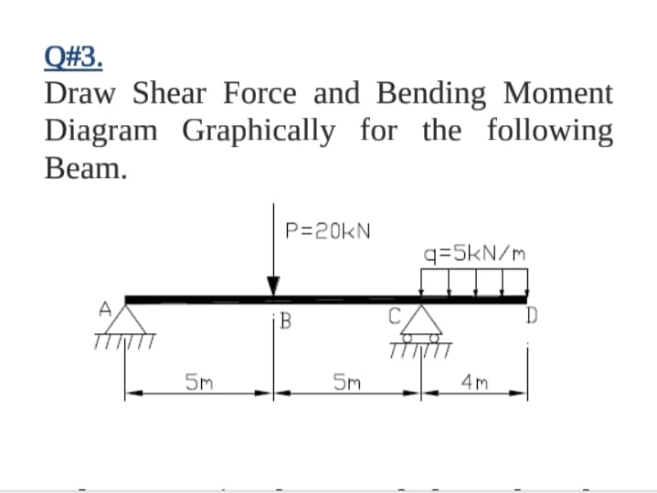
Transcribed Image Text:Q#3.
Draw Shear Force and Bending Moment
Diagram Graphically for the following
Вeam.
P=20KN
q=5kN/m
A,
5m
5m
4m
Expert Solution
This question has been solved!
Explore an expertly crafted, step-by-step solution for a thorough understanding of key concepts.

Step by step
Solved in 2 steps with 2 images

Knowledge Booster


Learn more about
Need a deep-dive on the concept behind this application? Look no further. Learn more about this topic, mechanical-engineering and related others by exploring similar questions and additional content below.Recommended textbooks for you
Mechanics of Materials (MindTap Course List)
Mechanical Engineering
ISBN:
9781337093347
Author:
Barry J. Goodno, James M. Gere
Publisher:
Cengage Learning
Mechanics of Materials (MindTap Course List)
Mechanical Engineering
ISBN:
9781337093347
Author:
Barry J. Goodno, James M. Gere
Publisher:
Cengage Learning