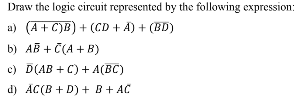
Draw the logic circuit represented by the following expression: a) (A+ C)B) + (CD + Ã) + (BD) b) AB + Č(A + B) c) D(AB+C) + A(BC) d) ĀC(B + D) + B + AČ


Q: 00 A-00 11 с-10 01 10 Z-0 Z-0 Too 01 10 01 10 11 01 00 10 В-01 D=11 Z-1 00 Z-1 1. Draw the state…
A: The solution for the above given question is given below:
Q: Draw the block & logic diagram of a one-bit cell circuit
A: Block diagram of a one-bit-cell circuit Logic diagram of a one-bit-cell circuit (using two NAND…
Q: SECTION D: DIGITAL LOGIC 1. Draw the logic circuit represented by the following expression: a)…
A: Logic Circuit is the pictorial representation of the Boolean expressions. Each logical operation is…
Q: A combinational logic circuit has three inputs with sequence A, B, and C and two outputs with…
A: 1. Boolean Algebra – This forms the algebraic expression showing the operation of the logic circuit…
Q: A combinational logic circuit has one output (F) and four inputs (a, b, c, and d). The circuit is…
A: Static one hazard can be detected using the following steps: Step-1: We draw the k-map using the…
Q: Design a combinational circuit with three inputs, x , y , and z , and three outputs, A, B, and C .…
A: Let's understand step by step: There are 3 inputs : x , y and z There are 3 outputs : A , B and C…
Q: 5) For the circuit shown in the figure below, find Z. MUX les, S A B A) Z = A OBC C) Z = AOBC B) Z =…
A: Here in this question we have given a multiplexer with output z.and we have asked to find the…
Q: Implement the sequential circuit with the state diagram given using D Flip-Flop elements and 8x1 MUX…
A: Answer: I have given answered in the handwritten format in brief explanation.
Q: Write Boolean Function for the following Logic circuit. OM The Boolean function for above logic…
A: Connecting the output of one logic gate to the input of another logic gate is how Boolean functions…
Q: Design a logic circuit with 3-bit inputs A, B, C that produces an output W, X, Y, Z that is equal to…
A:
Q: Truth Tables and Logic Gates /Circuits ~ - NOT 1. Derive truth tables for the following Boolean…
A: Question -1: Derive truth tables for the following Boolean expressions:a) ~(A + B)b) ~ A + (~ B)c)…
Q: Make a truth table for logical circuits shown below A B Y = A B+A C A Y B A AC
A: By the given circuit diagram, three basic gates are used: AND-Gate, OR-Gate, and NOT-Gate. Before…
Q: a) Implement the following Logic Circuit using C++. A, B, C, and D are the input bits while F…
A: Solution
Q: Given a combinational logic circuit whose input is a four-bit number and whose output is the 2's…
A: Given a combinational logic circuit whose input is a four-bit number and whose output is the 2's…
Q: Flip flop input and output equations for a sequential circuit with 3 flip flops (A, B and C), 2…
A:
Q: Consider the multiplexer based logic circuit shown in the figure W MUX 1 MUX 1 S, Select one: O a.…
A: For a 2 × 1 MUX is shown above, the output function F is expressed as: F = S̅1 I0 + S1I1 i.e. when…
Q: A logic circuit has three inputs (x2X,Xo) representing an unsigned binary number. The output D is…
A: A logic circuit has three input(x2,x1,x0) representing an unsigned binary number.The output D is…
Q: A combinational logic circuit has inputs A, B, C, D and E. The output Y is given by: fΠ M(15,31)…
A: Y = Π M(15,31) 15 = 01111 31 = 11111 In POS form, 100 is written as 0+1+1 That is for 1 we take…
Q: Design an equivalent logic circuit for the 4-bit Arithmetic and Logic Unit
A: Combinational Circuits Multiplexer (IC NO – 74151) The multiplexer or MUX is a virtual switch, also…
Q: Implement the following Logic Circuit using C++. A, B, C, and D are the input bits while F is the…
A: #include <iostream> using namespace std; int main() { int a,b,c,d,f; cout<<"enter…
Q: A combinational circuit with four inputs (A, B, C, D) and one output (Z) is designed as follows…
A:
Q: The output of a combinational logic circuit is F=A'D'+(A+B) (B'+C'). To remove the static one hazard…
A: If there is an accident in the digital circuit, it can cause temporary fluctuations in the circuit…
Q: A combinational circuit with four inputs (A, B, C, D) and one output (Z) is designed as follows…
A:
Q: Logic Circuit using C++. A, B, C, and D are th
A: Implement the following Logic Circuit using C++. A, B, C, and D are the input bits while F is the…
Q: 4. Draw a logic circuit for (A + B)'(C + D)C'.
A: According to the Question below the Solution:
Q: A combinational logic circuit has one output (F) and four inputs (a, b, c, and d). The circuit is…
A: The solution to the given problem is below.
Q: A Moore state machine consists of combinational logic circuits that determine(a) sequences (b)…
A: Д Divide circuit into combinational logic and state Proceed thru well-defined state sequence in…
Q: Q1) Draw the ladder diagram for the logic circuits A&B А: A AB в AB + AB AB
A: The gate given in the image is Exclusive-OR gate.
Q: The digital logic family which has the lowest propagation delay time is (A) ECL (B) TTL (C) CMOS…
A: Given: The digital logic family which has the lowest propagation delay time is (A) ECL(B) TTL(C)…
Q: Q: A combinational logic circuit has three inputs with sequence A, B, and C and two outputs with…
A: We need to draw the asm chart for the given circuit.
Q: 10000 I need to draw a circuit that compares the values from Q(n) with 10000. Please send an…
A: Lets see the solution.
Q: NOTE: USE LOGISIM TO DRAW THE LOGIC CIRCUITS A'BC'+DE+ABD • FG+E'A • A+B+CD+A'B
A: Truth table, in logic chart that shows the truth-value of one or more compound propositions for…
Q: 2) Design a 4-bit arithmetic circuit with two selection variables Sı and S2 that performs the…
A: Given The answer is given below.
Q: Design a combinational circuit with four inputs, w, x, y, and z, and four outputs, A, B, C and D.…
A: Design a combinational circuit with four inputs, w, x, y, and z, and four outputs, A, B, C and D.…
Q: Using suitable circuit diagrams, implement the following logic equations using CMOS i. f(xy) =…
A: Solution :: (i) Given function : f(x, y) = x + y For ( . ) operation nMOS --> series pMOS…
Q: A combinational logic circuit has three inputs with sequence A, B, and C and two outputs with…
A: A B C 0 0 0 0 0 1 0 1 0 0 1 1 1 0 0 1 0 1 1 1 0 1 1 1
Q: Identify that function generated by the logic circuit shown below: * :Dr A B D O F= A'B' + C + D OF=…
A:
Q: 1) Design an arithmetic circuit with one selection variables and two n-bit data inputs A and B. The…
A:
Q: Design a combinational circuit with three inputs x, y, z, and three outputs a, b, and c. When the…
A: Below is the truth table that full-fill the given relationship among the inputs x, y, z and outputs…
Q: 3. A logic circuit has three inputs (x,x,x,) representing an unsigned binary number. The output D is…
A: To design a logic circuit that has three inputs (X2X1X0) representing an unsigned binary number. The…
Q: Design a combinational circuit with three inputs, r, y, and z, and three outputs, A, B, and C. When…
A:
Q: A combinational logic circuit has an output F=bc'd+a'c'd'+acd+a'b'c. To
A: ab'd should be the right answer that can remove the static hazard as for solving combinational logic…
Q: Implement the logic function shown below using: F (A, B, C, D, E) = Em (0,5,7,11,15,16,18,25,29) 1-…
A:
Q: A combinational logic circuit has an output F=a'b'c+a'c'd'+bc'd+acd. To remove the static one hazard…
A:
Q: Given f (w, x, y, z) = II(0, 1,3, 5, 13), %3D the cl b) E c) W d) Write Y = f(w, x, y, z) in SOP…
A: In Sum Of Products form, the low value(0) is written with a bar while the high value(1) is written…
Q: 1- In the following sequential circuit. There are 2 D FF (A and B), 2 inputs (x and y), and 1 output…
A: In order to make the state diagram we need the state table. We will create te state table according…
Q: Q. A combinational logic circuit with three inputs A,B and C and one outputs F presented by the…
A:
Q: Example 3: Design a logic circuit whose output is HIGH only when a majority of the inputs A, B and C…
A: Since you have asked multiple questions, we will solve the first question for you. If you want any…


Trending now
This is a popular solution!

Step by step
Solved in 2 steps with 2 images


- Being X and Y of a consecutive circuit with 2 D flip flops, A and B.It has 2 inputs and 1 output as Z. DA= X'Y + XADB = X'B + XAZ=B a) Draw the logic diagram of the circuit.b) Create the state table of the circuit.c) Draw the state diagram of the circuit.Draw the logic diagram of the digital circuit specified by the following Verilog description: module Circuit_C (y1, y2, y3, a, b);output y1, y2, y3;input a, b;assign y1 = a || b;and (y2, a, b);assign y3 = a && b;endmoduleImplement the following Logic Circuit using C++. A, B, C, and D are the input bits while F is the output bit function.
- Design a combinational logic circuit that takes a 3–bit input and has one output P. The P output should be active high only when the inputs corresponds to a prime number Note: the prime numbers: Prime numbers are 2, 3, 5, 7… Select one: a. P= AC+B b. P= A'C+A'B c. P= AC+A'B d. P= AC+A'B'Draw a detailed logic diagram for a 4-bit Tiny ALU circuit, labeling the two bit Op signal inputs as Op1 and Op0, where zero is the least significant bit. Write the logic expression for the circuit (you will need expressions for the four output signals Out3, Out2, Out1, and Out0 in terms of the six input signals).Draw a logic circuit that would process all subtraction operation using simple addition
- Design a logic circuit to implement the operation specified in the truth table given below. Truth table INPUT Output Product Term ABC X 000 001 010 011 100 101 110 111 0 0 0 1 0 1 1 0 A’BCAB’C ABC’let consider 5 different outputs in combinational circuit/ Digital Logic Design For example x=1 y= 0 a =1 b= 1 c=0 Design a single output schema which take the 5 different outputs into a single 5 bit output Y[4:0] Y output will be for example 5 bits 10110Truth Tables and Logic Gates /Circuits~ - NOT1. Derive truth tables for the following Boolean expressions:a) ~(A + B)b) ~ A + (~ B)c) (~ A) + Bd) (~ A). (~ B)e) (~ A). (A + (~ B)) 2. Derive truth tables for:a) A.B + (~C)b) A. (BC)c) (AB).Cd) (~ A) .(B + C)e) ~(AB) + C 3. Derive truth tables for the following; inputs are A, B and C.a) W is True if an even amount of inputs is True, and False otherwise.b) W is True if exactly one input is true, and False otherwise.c) W is true if A and C are the same, and False otherwise. 4. Draw the logic circuits for the following Boolean expressions:a) W = (AB) + (NOT C)b) X = (~A). (B + C)c) Y = ~(AB) + C
- A sequential circuit with two D flip flops A and B, two inputs x and y and one output z is specified by the following next state and output equation: A(t+1) = x’y + xA B(t+1) = x’B + xA z = B a) Draw the logic diagram of the circuit b) List the state table for the sequential circuit c) Draw the corresponding state diagramA combinational circuit with four inputs (A,B,C,D) and one output (Z) is designed as follows using an 8:1 multiplexer. Inputs A,B,C are connected to the select lines ?S2, S1, S0 respectively. Multiplexer has the following values connected to the data inputs: I0,I6 =1; I1,I3 =D; I2,I5 =0; I4,I7 =D’ Write the simplest logic expression of the circuit realized above Z= f(A, B, C, D)Draw the non-abbreviated logic diagram for the following Boolean expressions. (You may use XOR gates.) A) ((a’)’)’C) a’b + ab’F) ((ab XOR b’) + a’b)’K) (abc’) + (a’ b’ c’)’N) (((a + b)’ + c)’ + d)’