3. A logic circuit has three inputs (x,x,x,) representing an unsigned binary number. The output D is required to be 1 if the input number is divisible by 2 or by 3 (i.e. if the quotient is an integer). Design the required logic.
Q: Design a logic circuit that controls an elevator door in a three-story building. M is a logic signal…
A:
Q: A: Design an arithmetic circuit with one selection variable S and two n-bit data inputs A and B. The…
A: A: Design an arithmetic circuit with one selection variable S and two n-bit data inputs A and B. The…
Q: b) Design a logic circuit that takes two inputs A, B and produces an output X such that X is 1(high)…
A: Objective: A logic circuit should be designed to generate an output X depending on two input…
Q: SECTION D: DIGITAL LOGIC 1. Draw the logic circuit represented by the following expression: a)…
A: Logic Circuit is the pictorial representation of the Boolean expressions. Each logical operation is…
Q: A combinational logic circuit has one output (F) and four inputs (a, b, c, and d). The circuit is…
A: Lets see the solution in the next steps
Q: A combinational logic circuit has three inputs with sequence A, B, and C and two outputs with…
A: 1. Boolean Algebra – This forms the algebraic expression showing the operation of the logic circuit…
Q: Q1: By using the Karnaugh map method, design a logic circuit with an input of 4- bit (ABCD) and one…
A:
Q: Define and explain 4-bit binary adder-subtractor logic circuit below. Give the detailed theoretical…
A: A Binary Adder-Subtractor is a circuit capable of both the addition and subtraction of binary…
Q: öaalg äbäi A combinational logic circuit has one output (F) and four inputs (a, b, c, and d). The…
A: A combinational logic circuit has one output(F) and four inputs (a, b, c and d) the circuit is…
Q: Q1 D ck w Q2 ck Clock- N 18
A: The, answer has given below:
Q: Q2) Design a logic circuit that detects the inputs divisible by 2 or 3 in 4-bit data (0 is divisible…
A: Let's start with the assuming the 4-bit number as ABCD (0000-1111) with 1st bit as A. Now, except 1,…
Q: (a) Draw a logic circuit for the case where the output, ENABLE, is HIGH only if the inputs, ASSERT…
A: Given: a) Draw a logic circuit for the case where the output, ENABLE, is HIGH only if the inputs,…
Q: Write Boolean Function for the following Logic circuit. OM The Boolean function for above logic…
A: Connecting the output of one logic gate to the input of another logic gate is how Boolean functions…
Q: Draw logic diagrams of the circuits that implement the original and simplified expressions in…
A: a. Given expression: ( x + y ) ′ ( x ′ + y ′ ) Logic diagram:…
Q: 1. Show the logic circuit implementation of the state machine described by the state diagram below.…
A:
Q: SOW Ex level clasing level closino D The train only comes. from the right. The length of the train <…
A: The train only comes from the right.The length of the train <x1 and x0 distance between.Design…
Q: a. Complete the truth table for the logic circuit shown below. b. Write the Boolean expression for…
A: As per our guidelines, we are supposed to answer only one question. Kindly repost the remaining…
Q: The output of the logic circuit is ... A exnor B A or B A and B A exor B None of this
A: Objective: Given a logic circuit involving 2-input variables. This logic circuit uses three NAND…
Q: Q1: For the state diagram shown below write the state table and design logic circuit
A: Here let's assign a binary value to each state Start=000 First=001 Second=010 Delay=011 Success=100
Q: Question 2 a) Write a boolean expression for the following combinational logic circuit and draw the…
A: As per barltbeby guidlines only first question is answered.
Q: 3. Given the Boolean expression in SOP form, fill in the truth table. Then draw the logic circuit…
A: The answer is in step 2:
Q: a) Implement the following Logic Circuit using C++. A, B, C, and D are the input bits while F…
A: Solution
Q: 2. Realize the logic circuits which implement the following Boolean expression, simplify the…
A:
Q: Draw logic diagrams of the circuits that implement the original and simplified expressions…
A:
Q: A sequential circuit with two D flip-flops, A and B; two inputs, x and y; and one output, Z, is…
A: a) The logic diagram of the circuit is given by:
Q: Design a logic circuit that controls an elevator door in a three-story building. The circuit has…
A:
Q: 25) Neatly draw the logic circuit for the expression below. Do not minimize or change the…
A:
Q: A combinational logic circuit has an output F=a'b'c+a'c'd'+bc'd+acd. To remove the static one hazard…
A: a combinational logic circuit has an output F=a'b'c+a'c'd'+bc'd+acd To remove the static one…
Q: A logic circuit has three inputs (x2X,Xo) representing an unsigned binary number. The output D is…
A: A logic circuit has three input(x2,x1,x0) representing an unsigned binary number.The output D is…
Q: 1. Design a logic circuit that has 3 inputs A, B, and Cand one output F. The output of the circuit…
A:
Q: Q1\ Design Logic Circuit and Write the Truth Table for Expressions: 1. A + B [C +A (B +C)] 2. (ĀB +…
A: Note: Here, θ symbol has been used as XNOR operation. The details operation has been given in step…
Q: 5-Draw the logic circuit represented the following truth table. 38 INPUT A INPUT B INPUT C OUTPUT X…
A:
Q: Given the following logic circuit: Do A B a) Find the output value at the points A, B, and C. b)…
A: As per our Guidelines we are supposed to answer first question only.Kindly Repost another question…
Q: Question: Implement the following Logic Circuit using C++ program. A, B, C, and D are the input bits…
A: Input : Given the boolean values of A, B, C, D. Output : The output value of F.
Q: Create a Truth Table and draw the logic circuit for (p ∨¬r) ∧ (¬p ∨ (q ∨¬r)).
A: A truth table is a logical table that determines whether or not a compound assertion is true.…
Q: Design a combinational circuit with four inputs, w, x, y, and z, and four outputs, A, B, C and D.…
A: Lets see the solution.
Q: Write a logic statement that corresponds with the given logic circuits:
A: Given logic circuit contains three input variables A, B and C and one output variables X. This…
Q: V. Problem Šolving: 1. Find the truth table for the logic circuit shown below. Авс F 0 0 0 0 0 1 0 1…
A: The gates that are shown in the diagram are said to be XOR gates These gates take 2 bits as inputs…
Q: Logic Circuit using C++. A, B, C, and D are th
A: Implement the following Logic Circuit using C++. A, B, C, and D are the input bits while F is the…
Q: Question 8) Design a logic circuit to decode the binary string A=0101, Write the output equation…
A: Decider is a combinational circuit which has n input line and 2n output lines. X and Y are input…
Q: 4. Draw a logic circuit for (A + B)'(C + D)C'.
A: According to the Question below the Solution:
Q: Q: A combinational logic circuit has three inputs with sequence A, B, and C and two outputs with…
A: We need to draw the asm chart for the given circuit.
Q: A combinational logic circuit has three inputs with sequence A, B, and C and two outputs with…
A: A B C 0 0 0 0 0 1 0 1 0 0 1 1 1 0 0 1 0 1 1 1 0 1 1 1
Q: 1. Find the truth table for the logic circuit shown below. Авс F 0 0 0 0 0 1 0 1 0 0 1 1 10 0 1 0 1…
A: The gates that are shown in diagram are said to be XOR gates These gates takes 2 bits as inputs and…
Q: A combinational logic circuit has three inputs with sequence A, B, and C and two outputs with…
A: Question is based on ASM chart.
Q: Draw a logic circuit that performed by this logic expression: Ā·(B + C) · D ·E = Y
A:
Q: 3. Design the Full Adder combinational logic. Full Adder has 3 inputs and two outputs, Sum and a…
A: Please give positive ratings for my efforts. Thanks. ANSWER
Q: A combinational logic circuit has one output (F) and four inputs (a, b, c, and d). The circuit is…
A: Static hazard takes place when change in an input causes the output to change momentarily before…
Q: Draw the non-abbreviated logic diagram for the following Boolean expressions. (You may use XOR…
A: We are authorized to answer three subparts at a time since you have not mentioned which part you are…
Q: Example 3: Design a logic circuit whose output is HIGH only when a majority of the inputs A, B and C…
A: Since you have asked multiple questions, we will solve the first question for you. If you want any…
Simplify the given functions using Boolean Algebra and draw the logic circuit.
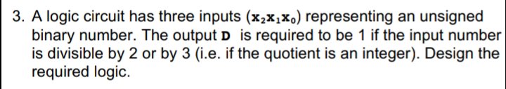
Trending now
This is a popular solution!
Step by step
Solved in 2 steps with 19 images
- Write a logic statement that corresponds with the given logic circuits:DIGITAL LOGICDraw the logic diagram corresponding to the following Boolean expression without simplifying it: F = A + BC + (A + B')(B + C')Draw logic diagram of the circuit that implement the original and simplified expression in part (A) above
- Create 2 logic diagrams with at least 4 inputs using at least 3 logic gates and provide their corresponding Boolean expression and truth table.Being X and Y of a consecutive circuit with 2 D flip flops, A and B.It has 2 inputs and 1 output as Z. DA= X'Y + XADB = X'B + XAZ=B a) Draw the logic diagram of the circuit.b) Create the state table of the circuit.c) Draw the state diagram of the circuit.QUESTION A logic circuit implements the following Boolean function: F = A'C + AC'D' It is found that the circuit input combination A = C = 0 can never occur. Find a simpler expression for F using the proper don’t care conditions. Design the logic circuit using the expression you find.
- Draw logic diagram of the circuit that implement the original and simplified expression in part 4. This is included with part 4 aboveDesign a circuit to implement the following truth table, where A and B are inputs and Z is the output. Give the Boolean equation that implements the circuit in the space provided. There may be more than one possible correct answer. You only need to list one possible correct answer. Input Output A B Z 0 0 1 0 1 0 1 0 1 1 1 1Draw the logic diagram of the digital circuit specified by the following Verilog description:
- X = 1Digital Logic Design1. write a truth table using this symbol: --> 2. write the inputs for the truth table to the left of the --> and write the outputs for the truth table to the right of the --> 3. write the compliment, or NOT using ' Given the following Boolean equation: F = A XOR B XOR C XOR D that represents a digital logic circuit where the output is F and the inputs A, B, C, and D, write the truth table for the Boolean equation.The logic circuit below is supposed to be designed to produce the truth table also shown below. However, there is a component missing. Which type of component is missing?