Draw the output voltages of each rectifier for the indicated input voltages, as shown in Figure 2–24. The IN4001 and 1N4003 are specific rectifier diodes.
Draw the output voltages of each rectifier for the indicated input voltages, as shown in Figure 2–24. The IN4001 and 1N4003 are specific rectifier diodes.

Electricity for Refrigeration, Heating, and Air Conditioning (MindTap Course List)
10th Edition
ISBN:9781337399128
Author:Russell E. Smith
Publisher:Russell E. Smith
Chapter12: Electronic Control Devices
Section: Chapter Questions
Problem 4RQ: What is the difference between a diode and rectifier?

Related questions
Question
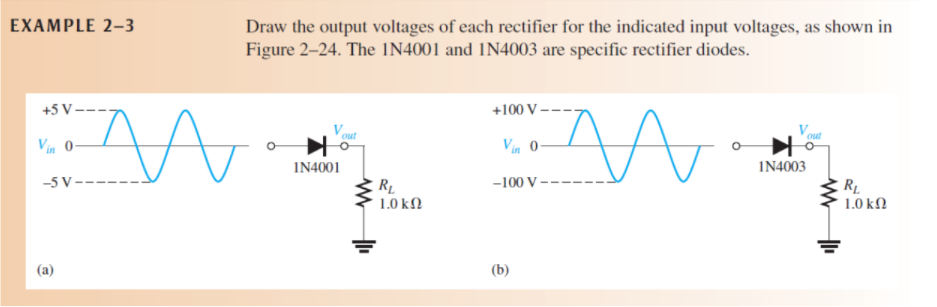
Transcribed Image Text:EXAMPLE 2–3
Draw the output voltages of each rectifier for the indicated input voltages, as shown in
Figure 2–24. The IN4001 and IN4003 are specific rectifier diodes.
+5 V -
+100 V -
out
out
Vin 0-
Vin 0-
IN4001
IN4003
-5 V -
-100 V
R1
1.0 kN
1.0 kN
(a)
(b)
Expert Solution
This question has been solved!
Explore an expertly crafted, step-by-step solution for a thorough understanding of key concepts.

Step by step
Solved in 2 steps with 2 images

Knowledge Booster


Learn more about
Need a deep-dive on the concept behind this application? Look no further. Learn more about this topic, electrical-engineering and related others by exploring similar questions and additional content below.Recommended textbooks for you
Electricity for Refrigeration, Heating, and Air C…
Mechanical Engineering
ISBN:
9781337399128
Author:
Russell E. Smith
Publisher:
Cengage Learning

Electricity for Refrigeration, Heating, and Air C…
Mechanical Engineering
ISBN:
9781337399128
Author:
Russell E. Smith
Publisher:
Cengage Learning