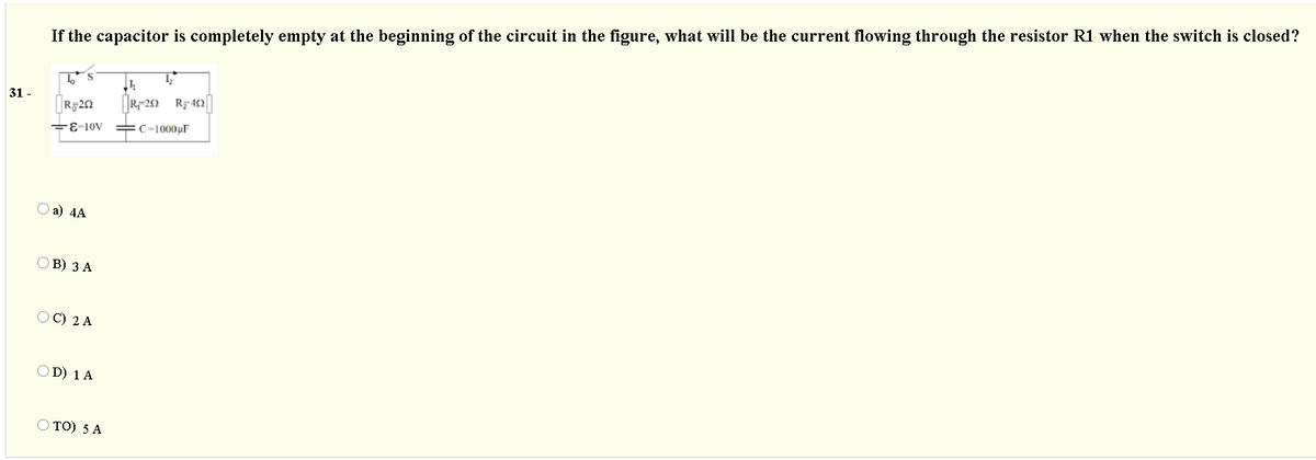
e capacitor is completely empty at the beginning of the circuit in the: 10v C-1000pF


Q: a capacitor has the capacitance of 20uf and a phase diff of 10 degrees it is inserted in series with…
A: Initial Value of Resistance Ri=100 Ω Capacitance, C=20 μF Phase Difference ϕ=100 Frequency, f= 50 Hz
Q: An RC circuit has an emf of 100 volts, a resistance of 5 ohms, a capacitance of 0.02 farad, and an…
A:
Q: For the given circuit the values of C1=6 µF, C2=14 UF, C3=5 uF and C4=100 µF : C3 B The value of…
A:
Q: In the circuit shown in fiqure the switch is closed at time (t=0). The rate of change of current di…
A: Referring to the given circuit, at time t=0-, the switch will be open as nothing mentioned in the…
Q: or the following RLC circuit, powered by a direct current voltage source of! 0 V, answer with V or F…
A:
Q: The two capacitors shown in the figure have been connected for some time and have reached their…
A: The two capacitors shown in Figure have been connected in series
Q: For the given circuit the values of C1=5 µF, C2=13 pF, C3=7 pF and C4=12 pF C4 C2 The value of…
A:
Q: A 100-mH inductor is connected in parallel to the series connection of a variable resistor R and a…
A:
Q: Find the value of iL (0+) in the following circuit: Consider that the function μ (t) corresponds…
A: Resistors, inductors and capacitors form an integral part of any electrical circuit. A source,…
Q: Underdamping
A:
Q: A series RLC circuit containing a resistance of 12 Q, an inductance of 0.15 H and a capacitor of 100…
A: we need to find out total circuit impedance, total circuit current, voltage across R, L and C.
Q: The current through a 10-mH inductor is 10e-t/2 A. Find the voltage and the power at t = 5 s. The…
A: In this question we will find power and voltage through inductor...
Q: The current source at the terminals of the 2 capacitors is of 120e- FA for the initial values of V,…
A:
Q: 5. A voltage of 35 V is applied across a R-C series circuit. If the voltage across the resistor is…
A: Given data, V = 35 V. VR = 21 V.
Q: The capacitor in the circuit is set to 1 F and the inductor is 10 H. C HE + vc Зи(-1) А ( ) 12 Ω –…
A:
Q: The capacitor in the circuit is set to 1 F and the inductor is 9 H. HE + Vc 3u(-t) A ( , ) 12 -2i,…
A: At steady state capacitor acts as open circuit and inductor acts as short circuit. Capacitor does…
Q: The voltage on 3 mH inductor is shown in * .figure. Find and draw the current i 15.0 t, ms -30.0
A: Given: Inductance L=3 mH From the voltage waveform, VL=15 V0<t<2 ms-30 V2<t<4 ms
Q: 2) Please find the time constant and capacitance value (C) of a simple RC circuit by using ita…
A: To solve above question, one should understand the behavior of Inductor and capacitor in DC circuit.…
Q: 4. The circuit is in DC steady state at t =0". At t=0 the switch is opened. 24 V 0.25F
A: This question is from "Networks". Under which we are going to study about the transient response of…
Q: In the circuit shown above, the initial voltage across capacitor is 2 V and I is a unit step current…
A: The required parameters can be obtained by considering the state of the circuit at t=0 and after…
Q: Question 1 The current source at the terminals of the 2 capacitors is of 120e-St uFA for the initial…
A: In this question, Current in the capacitor is given. Find the voltage across the V2. All…
Q: Consider the following circuit. The initial voltage across the capacitor is 15V and the initial…
A: Given the circuit: Given the initial voltage across capacitor equal to 15 V and the initial current…
Q: Analyze a series R.L.C. circuit consisting of 40 resistor, 22.5 H inductor and a capacitor with 200V…
A: According to question:
Q: 100-mH inductor is connected in parallel to the series connection of a variable resistor R and a…
A:
Q: Q5: You have given the following Differential Equation (D.E): (1(t)) + 4 (i() + 5i(t) = 5u(t) di(0)…
A:
Q: 2. Capacitor Circuits C1=8µF A - C4=5µF Cs=2µF, C2=2µF В C3=1µF What is the capacitance between…
A: Given Capacitance circuit find equivalent of the circuit
Q: For a series RLC Circuit the inductor is variable. Source voltage is 200√2 sin100nt. Maximum current…
A:
Q: Q6 ») sketch the pole-zero map of G (s) G(s) = (s+2)(s-3) (s+3+2j)(s+3-2))(s+4)
A: Note: We are authorized to answer one question at a time since you have not mentioned which question…
Q: + -5 (sui)7 5. 10- suu d = Copacitor is shown in the figure. Find the
A: we need to find the energy stored in the capacitor for various time instant given in the circuit.
Q: A series RL circuit has a 1H inductor. Determine the value of R so that the stored energy is reduced…
A: Energy stored in inductor = 0.5 L(current)2. Given inductor = 1 H .
Q: The voltage on 3 mH inductor is shown * .in figure. Find and draw the current i 15.0 t, ms -30.0
A: Given voltage across inductor is shown below. Given inductor value L=3mH. The current through…
Q: The voltage accross 3-µF capacitor is shown Determine the current iſt) graphically and label all…
A: The circuit is drawn as:
Q: For a standard capacitor with c=134μF: If the stored energy is w(t)=26.5e^(−575t) μJ for t>0,…
A: To determine the value of current in capacitor of 134μF and energy stored in it is…
Q: The current in a 150 uH inductor is : j
A:
Q: The equivalent capacitance at terminal in the circuit given is 30 F, then the valu C is а a o- = 14…
A: In this question , we have to find unknown capacitance...
Q: 2. If the circuit has a resistance R is 100 the inductor L is .5H and the capacitor C is 5 µf what…
A:
Q: Solve the elementary application of Differential equation: A series RL circuit with R = 50 Ohms and…
A:
Q: Find the equivalent capacitance when series connected 5microfarad and 20microFarad capacitors are…
A: Resistors, inductors and capacitors form an integral part of any electrical circuit. A source,…
Q: Determine the admittance of the below circuit looking at terminal a and b. Coverage: Basic RLC…
A:
Q: In a series RLC circuit, the larger reactance determines the net reactance of the circuit. Select…
A:
Q: 8. An clectrical circuit (without resistor) has an inductor of 2 henry and capacitor of capacitance…
A:
Q: 5. A series RLC circuit is excited by a 100-V, 79.6-Hz source and has the following C = 5…
A: It is given that: V=100 Vf=79.6HzR=100ΩL=1HC=5μF
Q: 6v 0.4 F 72 Ω 72 2 In the circuit in the figure, the capacitor Since the initial condition voltage…
A:
Q: The value of the capacitor current for the circuit below is:
A: Given data: R=10 kΩ
Q: 3.) A parallel RLC circuit with R 50 2, L = 55.6 mH, and C = 200 microfarad, has an initial charge…
A:
Q: The switch in the figure below is closed at t = 0. The initial voltage on the capacitor is ve(0) =…
A: In this question , we will find. Capacitor voltage after switch close...And current is…
Q: The capacitor in the circult of Figure below is Initially uncharged. Find vo) for t> 0. 550) V , IF
A:
Q: A 0.33- uF capacitor is in parallel with a 0.15 uF and a 220,000-pF capacitor. What is the total…
A:

Step by step
Solved in 2 steps with 2 images


- An R-L series circuit contains two resistors and two inductors. The resistors have values of 120 and 300 . The inductors have reactive values of 220 and 470 . Find impedance.This circuit is connected to a 1000-Hz line. The resistor has a voltage drop of 185 V. the inductor has a voltage drop of 740 V, and the capacitor has a voltage drop of 444 V. The circuit has an apparent power of 51.8 VA. ETITZVA51.8PFER185VIRRPEL740VILXLVARsLLEC444VICXCVARsCCYou are an electrician working in an industrial plant. You discover that the problem with a certain machine is a defective capacitor. The capacitor is connected to a 240-volt AC circuit. The information on the capacitor reveals that it has a capacitance value of 10 mF and a voltage rating of 240 VAC. The only 10-mF AC capacitor in the storeroom is marked with a voltage rating of 350 WVDC. Can this capacitor be used to replace the defective capacitor? Explain your answer.
- An R-L series circuit contains two resistors and two inductors. The resistors dissipate powers of 96 watts and 125 watts. The inductors have reactive powers of 100 VARs and 78 VARs. What is the power factor?In the circuit of the image, the capacitor is initially discharged, with the switch open. Values are in the second image.When time t = 0, the switch is closed. Which of these is correct: A. A lot of time has passed after the switch was closed. Now you open it, and set t = 0. When t = 5x10^-3 seconds, the current is 0.036AB. The current given by the battery when t = 5x10^-3(s) is 0.036AC. A lot of time has passed after the switch was closed. The current given by the battery is 0.01 A.D. A lot of time has passed after the switch was closed. Now you open it, and set t = 0. The time it takes the capacitor to decrease to 10% of its max charge, is 0.023 seconds.E. The current when t = 0 is 0.02AAnswer it clearly Show the complete solution An R-L-C series circuit has a current which lags the applied voltage by 45 degrees. The voltage across the inductance has maximum value equal o twice the maximum value of voltage across the capacitor. Voltage across the inductance is 300 sin (1000t) and R = 20 ohms Find the value of inductance, total impedance and capacitance.
- A series RC with R = 91-Ω and C =7-F connected across a 100 VDC source for a LONG TIME, what is the voltage across the capacitor? Write the values only (round to four decimal places).The capacitors are iinitially uncharged, and the switch is initially open. a) When the switch is first closed, what is the current through R2?A capacitor C is connected in parallel with a series combination of capacitors of 8 and 4 microF. The voltage drop across capacitor C is 12V. The 3 capacitors have been connected for sometime and have reached their present value. Find the voltage across the capacitor with 8 microF. A. 4V B. 9V C. 3V D. 8V
- topic : capacitors, inductors, source free and step respons RL & RC circuits could use some assistance answering no.4, kindly show me the complete process as it helps me understand the problem completely. thank youThe circuit has a current of 38 A flowing through the resistor, 22 A flowing through the inductor, and 7 A flowing through the capacitor. What is the total circuit current?There is no energy stored in the capacitor inthe circuit when switch 1 closes at t=0. Switch 2 closes 10microseconds later. Find vo(t) for t≥0