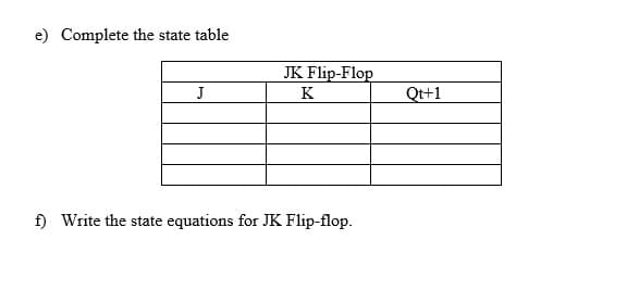
e) Complete the state table JK Flip-Flop J K Qt+1


Q: simplify the Boolean function, F=B’(CD’+A) + C’D(A’+B)
A: To simplify ,F=B'(CD'+A)+C'D(A'+B)
Q: Consider the circuit shown below R Qn clock X S The circuit acts as (A) output remains stable at “O"…
A:
Q: Sample Problem No. 1 00 Based on the given state diagram, design a sequential circuit using: 1/0 0/0…
A: Hello. Since your question has multiple sub-parts, we will solve the first three sub-parts for you.…
Q: Using positive edge T Flip Flop design synchronous circuit for the following state diagram? * 1 111…
A: Solution- The characteristic table- T Qn Qn+1 0 0 0 0 1 1 1 0 1 1 1 0 The excitation…
Q: Answer the following questions. Clearly show your work. (a) Figure Q.4.1 shows a negative edge…
A: The output of flipflop can be analysed based on the state of the input and the type of flipflop. The…
Q: a J-K Flip Flop, if the input J=1 and K=0, then its tput is
A:
Q: Fill in the correct Q values for the following T Flip-Flop exoitation table: Q' 1. 1. 1. 1.
A:
Q: 1. How many cascade MOD4 counter is needed to provide a decimal count of 33.333? A.16 B.8 C.4 D.2 2.…
A:
Q: b) Evaluate the minimised Boolean expressions required to implement the following 0-6 reset counter…
A: J-K flip flop- The J-K flip flop is the same as the S-R flip-flop with the addition of a clock input…
Q: Design a one-input, one-output sequence detector, which produces an output 1 every time the sequence…
A:
Q: Compute the following timing diagram for a rising -edge triggered S-R flip-flop. Assume Q begins at…
A: Write the truth table for the S-R flip flop.
Q: QUESTION 4 Two D fip flops are connected in Fig 4 with the timing dagrams for input CLK and D. D D1…
A:
Q: Design a synchronous counter using JK flip-flops to produce the following sequences. 3 5 1
A: According to the question, we need to design a synchronous counter, which follows the following…
Q: What is the output of the JK flip flop (i.e. Q(t +1)) in the following circuit when A= 1, B= 1, C=1?…
A: In this question we need to find a output of JK flip flops.
Q: TWO Questions (a) Draw the Logic Diagram and Truth table of a JK Flip-flop.
A: The relisation of JK flip flops can be achieved by two arrangements. One is with AND and NOR gate…
Q: How to connect these boolean expressions to IC CHIP CD4027 Jk flip flop 1 Ja = BCD Ka = D JK…
A: According to the question, for the given boolean function as shown below Jk flip flop 1 Ja = BCD Ka…
Q: simplify the boolean function E0 = AD’+B’C’D’+B’CD+BCD’+A’BC’D
A:
Q: CLK SR Q' 0 1 0 1 0 1 1 1 0 R
A:
Q: Name For J K Flip Flop shown below find the output Q if the initial value is '0' for the following…
A:
Q: Convert JK F.F to T F.F
A:
Q: Input Count 1 1 2 3
A:
Q: DESIGN THE SYNCHRONOUS COUNTER WITH THE FOLLOWING STATE TRANSITION DIAGRAM. USE J-K FLIP FLOP IN THE…
A:
Q: A flip-flop which has the following operating characteristic, will be designed as a synchronous…
A:
Q: HW : Plot the output waveform (Q) for T Flip-Flop : Clk Pre
A: To plot the waveform of Q of the negative edge trigger T Flip-flop is drawn with the help of the…
Q: ven the following sequential circuit Next Present State x =0 Input State Flip-Flop Inputs A B A B J…
A: Given the state diagram: 1. We need to complete the table as shown below: 2. We need to draw the…
Q: In a positive edge-triggered JK Flip-Flop, if the J input is 0 and the K input is 1, which value…
A:
Q: Design a Decade Counter (0 to 9) using JK Flip Flops. (All unused states are don’t care conditions)
A: Decade Counter: A binary coded decimal (BCD) is a digital counter that counts ten digits serially…
Q: Design the CHARACTERISTICS Table and EXCITATION Table for the given Flip-Flops and their respective…
A: (a) The given flipflop is an S-R flipflop as shown in the figure below: The truth table for this is…
Q: Q1) Design sequential cireuits with JK Flip-Flops to implement the following state diagram. 00 1/1…
A: We know that the excitation table of J-K flip flop is ad followes : Qn Qn+ J K 0 0 0 X 0 1…
Q: Consider the following Edge Triggered D Type Flip-Flop with Set (S), (R) and the D inputs. CK CK D
A: The explanation is as follows.
Q: A JK flip-flop with K=J' is equivalent to a: O a. JK-type flip-flop O b. T-type flip-flop Oc. D-type…
A:
Q: Complete the timing diagram for the J input to a nerative-edge triggered JK flip-flop. K Clock
A:
Q: Complete the timing diagram for the Jinput to a merative-edge triggered JK flip-flop. K Clock
A: From J K flip flop
Q: Design the circuit from the state diagram below using RS flip-flop. Hint: Do the state table first.…
A: I have explained the answer below steps
Q: obtained from an JKflip-flop by connecting J and K terminals together. b) SR Flip Flop AS (a) SR…
A:
Q: Design a counter to produce the following sequence. Use J-K flip-flops. 00, 10, 01, 11, 00, ...
A: Sequence should be 00, 10, 01, 11, 00 ....... Truth table is Present- State Next- State…
Q: Using J-K Flip Flop design a circuit that implements the machine whose state diagram is shown below.…
A:
Q: M K K GND (a) 田田 山山 CLK J 山 山出 K M (b)
A:
Q: Redesign the following flip flop circuit using JK flip flops only. SR D R FF FF clk clk-…
A: In this question we need to design the given flip flops using JK flip flops.
Q: a) Complete the timing diagram for the D input to a negative-edge triggered D flip-flop. D Clock b)…
A: Given D flip flop with negative edge triggering The truth table of the D- flip flop is By using…
Q: For the State Transition Table 91 92 919, x=0x 1 x0x 1 11 10 11 01 10 00 10 11 01 11 01 Design a…
A: The excitation table for D flip-flop is given by:
Q: Q4. Plot the output waveform Q for a JK Flip-Flop with positive going edge. Does it have any…
A: As per our guidelines we can only answer a single question at a time. Please resubmit the other…
Q: a) Complete the timing diagram for the D imput to a nerative-edge triggered D flip-flop. D Clock Q
A: Since you have asked multiple questions in a single request, we will be answering only the 1st…
Q: DESIGN THE SYNCHRONOUS COUNTER WITH THE FOLLOWING STATE TRANSITION DIAGRAM. USE J-K FLIP FLOP IN THE…
A: There are 8 states so total flip flop required is 3. Let the three states of flip flop be Q1Q2Q3.…
Q: Design the circuit of the following synchronous counter defined by the state transition diagram.…
A: This question belongs to digital electronics . It is based on the concept of designing of…
Q: Based on the state diagram below. 0/0 1/0 1/0 00 01 1/1 0/0 1/0 0/0 0/0 10 11 Draw a sequential…
A:
Q: The following is JK Flip-Flop characteristic table. Find A, B, C and D Flip-Flop Characteristic…
A: Here, Q(t) is represented as the present state of the J-K flip flop. And, Q(t+1) is represented as…
Q: QI// Design a scquential circuit whose state tables are specified in table below, using JK…
A:
Q: ign a counter with the count sequence 0, 1, 2, 4, 5, 6 using JK flip-flops. Fill in the following…
A:
Q: Synchronous Machine Design Example 1 Design a positive edge-triggered JK flip-flop using a positive…
A:

Step by step
Solved in 2 steps


- Design the asynchronous counter circuit using JK flip-flops, starting from the smallest decimal digit to the largest decimal digit in the following numbers. (1180501624)Design an Octal Counter with D flip-flops.a) Draw the state diagramb) Draw the state tablec) Draw the counter circuitDraw the diagram of a 2-bit asynchronous ripple counter using T flip-flops. Draw the diagram of a 5-bit ring counter using D flip-flop.
- 1) by creating the state table for the state diagram given below a) draw logic diagrams by designing Sequential Circuits with JK Flip flops. b)Draw logic diagrams by designing Sequential Circuits with D-Type Flip flops.1)Design a 3-bit binary gray code up/down counter using J-K Flip Flops. Draw the state table, state diagram and draw the logic circuit.d) Write down the transition table for T flip flop.e) Suppose, you want to design a 4-bit down counter which only counts the odd numbers.Write down the state table for the counter.
- Show the digital circuit diagram, output waveforms and truth table of a modulo-5 up counter using toggle flip-flops and explain the working principle.Design a Mode 14 asynchronous forward counter circuit. (Use JK or T type flip-flops) I designed the mode 11 forward counter circuit below (using JK or T type flip-flop) Can you draw a Mod 14 asynchronous forward counter circuit as in the photo?Design a 2-bit binary counter using: One SR and one JK flip flop.
- Obtain the state diagram for the following state machine. Consider that the flip flop above is the MSB.Given the state diagram and D flip-flop, derive the state table, Flip-flop input equation and output equation, and logical diagram.Determine the Q waveform for the flip-flop as seen in the figure below. Assume that Q = 0 initially.