earning Goal: Part A- Calculating the output voltage of a difference op-amp circuit o analyze difference op-amp circuits. efore proceeding, review difference op-amp circuits and the ideal p-amp assumptions. For the circuit shown (Figure 1), determine Vo when R1 = 8.2 kN , R2 = 40 kN , V; = 80 mV , V, = 80 mV , and Vec = 15 V . Express your answer to three significant figures and include the appropriate units. - View Available Hint(s) Hint 1. How to analyze the circui • Hint 2. Find the voltage division at the positive terminal of the op-amp What is the expression for voltage division at the positive terminal of the op-amp (V)? Express your answer in terms of R, R2, and V.. Vp = R+R, Vz Submit Previous Answers Answer Requested This voltage is the same as the voltage at the negative terminal of the op-amp. Templetes Symbols undo redo feset keyboard shortcuts hielp Vo = Value Units Submit Request Answer < 1 of 1> ure Part B - Design of a difference op-amp circuit For the circuit shown (Figure 1), determine R, such that Vo = m x (V, – V). Assume m = 3.5 and R2 = 20 kn and that the op-amp is in its linear region of operation. Express your answer to three significant figures. > View Available Hint(s) Templates Symbols Slape/Displacement Vector undo redo feset keyboard shortcuts help V. R1 =
earning Goal: Part A- Calculating the output voltage of a difference op-amp circuit o analyze difference op-amp circuits. efore proceeding, review difference op-amp circuits and the ideal p-amp assumptions. For the circuit shown (Figure 1), determine Vo when R1 = 8.2 kN , R2 = 40 kN , V; = 80 mV , V, = 80 mV , and Vec = 15 V . Express your answer to three significant figures and include the appropriate units. - View Available Hint(s) Hint 1. How to analyze the circui • Hint 2. Find the voltage division at the positive terminal of the op-amp What is the expression for voltage division at the positive terminal of the op-amp (V)? Express your answer in terms of R, R2, and V.. Vp = R+R, Vz Submit Previous Answers Answer Requested This voltage is the same as the voltage at the negative terminal of the op-amp. Templetes Symbols undo redo feset keyboard shortcuts hielp Vo = Value Units Submit Request Answer < 1 of 1> ure Part B - Design of a difference op-amp circuit For the circuit shown (Figure 1), determine R, such that Vo = m x (V, – V). Assume m = 3.5 and R2 = 20 kn and that the op-amp is in its linear region of operation. Express your answer to three significant figures. > View Available Hint(s) Templates Symbols Slape/Displacement Vector undo redo feset keyboard shortcuts help V. R1 =

Delmar's Standard Textbook Of Electricity
7th Edition
ISBN:9781337900348
Author:Stephen L. Herman
Publisher:Stephen L. Herman
Chapter18: Resistive-inductive Parallel Circuits
Section: Chapter Questions
Problem 13PP: In an R-L parallel circuit, IT=1.25 amps, R=1.2k, and XL=1k. Find IR

Related questions

Question
100%
Please help me with parts a and b
Transcribed Image Text:I Review I Constants
Learning Goal:
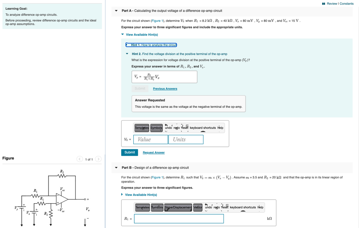
Part A - Calculating the output voltage of a difference op-amp circuit
To analyze difference op-amp circuits.
For the circuit shown (Figure 1), determine Vo when R1 = 8.2 kN , R2 = 40 kN , V½ = 80 mV , Vy = 80 mV , and Vcc = 15 V .
Before proceeding, review difference op-amp circuits and the ideal
op-amp assumptions.
Express your answer to three significant figures and include the appropriate units.
View Available Hint(s)
Hint 1. How to analyze the circui
Hint 2. Find the voltage division at the positive terminal of the op-amp
What is the expression for voltage division at the positive terminal of the op-amp (Vp)?
Express your answer in terms of R, R2 , and Vr.
R2
Vp
R1+R,
Submit
Previous Answers
Answer Requested
This voltage is the same as the voltage at the negative terminal of the op-amp.
Templates Symbols undo redo
Peset
keyboard shortcuts help
Vo =
Value
Units
Submit
Request Answer
Figure
1 of 1
Part B - Design of a difference op-amp circuit
R2
For the circuit shown (Figure 1), determine R1 such that Vo = m x (V½ – Vy) . Assume m = 3.5 and R2 = 20 kN and that the op-amp is in its linear region of
operation.
Express your answer to three significant figures.
R1
• View Available Hint(s)
R1
Templates Symbols Slope/Displacement Vector undo redo
Peset
keyboard shortcuts help
V.
R2
R1 =
Expert Solution
This question has been solved!
Explore an expertly crafted, step-by-step solution for a thorough understanding of key concepts.

This is a popular solution!

Trending now
This is a popular solution!

Step by step
Solved in 2 steps with 3 images

Knowledge Booster


Learn more about
Need a deep-dive on the concept behind this application? Look no further. Learn more about this topic, electrical-engineering and related others by exploring similar questions and additional content below.Recommended textbooks for you
Delmar's Standard Textbook Of Electricity
Electrical Engineering
ISBN:
9781337900348
Author:
Stephen L. Herman
Publisher:
Cengage Learning
Delmar's Standard Textbook Of Electricity
Electrical Engineering
ISBN:
9781337900348
Author:
Stephen L. Herman
Publisher:
Cengage Learning