Q3- Sketch the root locus of a unity feedback linear time invariant K(-7s+7) for (2s+6s+4s) control system of open loop transfer function: positive values of loop gain and damping ratio 0.56.
Q3- Sketch the root locus of a unity feedback linear time invariant K(-7s+7) for (2s+6s+4s) control system of open loop transfer function: positive values of loop gain and damping ratio 0.56.

Power System Analysis and Design (MindTap Course List)
6th Edition
ISBN:9781305632134
Author:J. Duncan Glover, Thomas Overbye, Mulukutla S. Sarma
Publisher:J. Duncan Glover, Thomas Overbye, Mulukutla S. Sarma
Chapter12: Power System Controls
Section: Chapter Questions
Problem 12.3P

Related questions
Question
i need the answer quickly
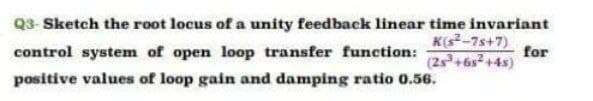
Transcribed Image Text:Q3- Sketch the root locus of a unity feedback linear time invariant
K(-7s+7)
for
(2s+6s+4s)
control system of open loop transfer function:
positive values of loop gain and damping ratio 0.56.
Expert Solution
This question has been solved!
Explore an expertly crafted, step-by-step solution for a thorough understanding of key concepts.

Step by step
Solved in 4 steps with 4 images

Recommended textbooks for you
Power System Analysis and Design (MindTap Course …
Electrical Engineering
ISBN:
9781305632134
Author:
J. Duncan Glover, Thomas Overbye, Mulukutla S. Sarma
Publisher:
Cengage Learning
Power System Analysis and Design (MindTap Course …
Electrical Engineering
ISBN:
9781305632134
Author:
J. Duncan Glover, Thomas Overbye, Mulukutla S. Sarma
Publisher:
Cengage Learning