Exercise: For the circuit of Figure 2 with the parameters of Table 2, what is the time constant associated with the opening of the switch? ww С R2 4 V Figure 2: Second RC circuit Table 2: Component values for Figure 2 R2 3 kΩ R1 1 k2 С 0.1 μF
Exercise: For the circuit of Figure 2 with the parameters of Table 2, what is the time constant associated with the opening of the switch? ww С R2 4 V Figure 2: Second RC circuit Table 2: Component values for Figure 2 R2 3 kΩ R1 1 k2 С 0.1 μF

Delmar's Standard Textbook Of Electricity
7th Edition
ISBN:9781337900348
Author:Stephen L. Herman
Publisher:Stephen L. Herman
Chapter33: Single-phase Motors
Section: Chapter Questions
Problem 1PA

Related questions
Question
100%
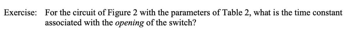
Transcribed Image Text:Exercise:
For the circuit of Figure 2 with the parameters of Table 2, what is the time constant
associated with the opening of the switch?
Transcribed Image Text:ww
С
R2
4 V
Figure 2: Second RC circuit
Table 2: Component values for Figure 2
R2
3 kΩ
R1
1 k2
С
0.1 μF
Expert Solution
This question has been solved!
Explore an expertly crafted, step-by-step solution for a thorough understanding of key concepts.

This is a popular solution!

Trending now
This is a popular solution!

Step by step
Solved in 5 steps with 5 images

Recommended textbooks for you
Delmar's Standard Textbook Of Electricity
Electrical Engineering
ISBN:
9781337900348
Author:
Stephen L. Herman
Publisher:
Cengage Learning
Delmar's Standard Textbook Of Electricity
Electrical Engineering
ISBN:
9781337900348
Author:
Stephen L. Herman
Publisher:
Cengage Learning