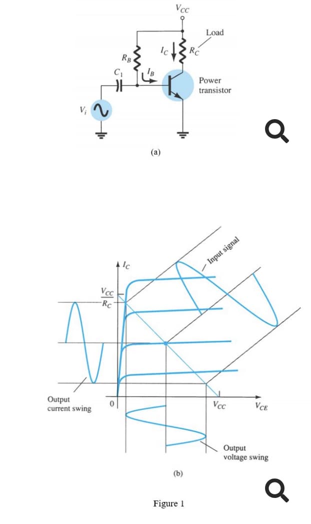
Figure 1(a) shows a series fed class A amplifier circuit. In order to achieve the maximum efficiency, the Q point must be located at the center of the DC load line as shown in Figure 1(b). This generates the maximum output current swing of Vcc Icmax (p – p) = RC and the maximum output voltage swing is VCEmax (p – p) = Vcc Assume that the maximum input de power is Vềc Pimax(dc) = Vcc!cQ(max)=Vcc \7' Rc. %3D %3D 2Rc Find the maximum efficiency, 7 of this circuit.
Figure 1(a) shows a series fed class A amplifier circuit. In order to achieve the maximum efficiency, the Q point must be located at the center of the DC load line as shown in Figure 1(b). This generates the maximum output current swing of Vcc Icmax (p – p) = RC and the maximum output voltage swing is VCEmax (p – p) = Vcc Assume that the maximum input de power is Vềc Pimax(dc) = Vcc!cQ(max)=Vcc \7' Rc. %3D %3D 2Rc Find the maximum efficiency, 7 of this circuit.

Introductory Circuit Analysis (13th Edition)
13th Edition
ISBN:9780133923605
Author:Robert L. Boylestad
Publisher:Robert L. Boylestad
Chapter1: Introduction
Section: Chapter Questions
Problem 1P: Visit your local library (at school or home) and describe the extent to which it provides literature...

Related questions
Question
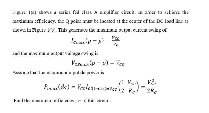
Transcribed Image Text:Figure 1(a) shows a series fed class A amplifier circuit. In order to achieve the
maximum efficiency, the Q point must be located at the center of the DC load line as
shown in Figure 1(b). This generates the maximum output current swing of
Icmax (p – p)
RC
and the maximum output voltage swing is
VCEmax(p – p) = Vcc
Assume that the maximum input de power is
(1 Vcc
Pimax(dc) = Vcc!cQ(max)=Vcc \2° Rc.
2Rc
Find the maximum efficiency, 7 of this circuit.
Transcribed Image Text:Vcc
Load
Ic
RB
Power
transistor
V;
(a)
- Input signal
Vcc
-Rc
Output
current swing
Vcc
VCE
Output
voltage swing
(b)
Figure 1
Expert Solution
This question has been solved!
Explore an expertly crafted, step-by-step solution for a thorough understanding of key concepts.

Step by step
Solved in 2 steps with 2 images

Knowledge Booster


Learn more about
Need a deep-dive on the concept behind this application? Look no further. Learn more about this topic, electrical-engineering and related others by exploring similar questions and additional content below.Recommended textbooks for you
Introductory Circuit Analysis (13th Edition)
Electrical Engineering
ISBN:
9780133923605
Author:
Robert L. Boylestad
Publisher:
PEARSON

Delmar's Standard Textbook Of Electricity
Electrical Engineering
ISBN:
9781337900348
Author:
Stephen L. Herman
Publisher:
Cengage Learning

Programmable Logic Controllers
Electrical Engineering
ISBN:
9780073373843
Author:
Frank D. Petruzella
Publisher:
McGraw-Hill Education
Introductory Circuit Analysis (13th Edition)
Electrical Engineering
ISBN:
9780133923605
Author:
Robert L. Boylestad
Publisher:
PEARSON
Delmar's Standard Textbook Of Electricity
Electrical Engineering
ISBN:
9781337900348
Author:
Stephen L. Herman
Publisher:
Cengage Learning
Programmable Logic Controllers
Electrical Engineering
ISBN:
9780073373843
Author:
Frank D. Petruzella
Publisher:
McGraw-Hill Education

Fundamentals of Electric Circuits
Electrical Engineering
ISBN:
9780078028229
Author:
Charles K Alexander, Matthew Sadiku
Publisher:
McGraw-Hill Education

Electric Circuits. (11th Edition)
Electrical Engineering
ISBN:
9780134746968
Author:
James W. Nilsson, Susan Riedel
Publisher:
PEARSON

Engineering Electromagnetics
Electrical Engineering
ISBN:
9780078028151
Author:
Hayt, William H. (william Hart), Jr, BUCK, John A.
Publisher:
Mcgraw-hill Education,