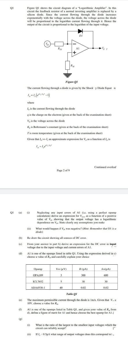
Figure QI shows the circuit diagram of a "Logarithmic Amplifier". In this circuit the feedback resistor of a normal inverting amplifier is replaced by a silicon diode. Since the current flowing through the diode increases exponentially with the voltage across the diode, the voltage across the diode will be proportional to the logarithm current flowing through it. Hence the output of the circuit is proportional to the logarithm of the input voltage. QI DI Res AI RM Figure QI The current flowing through a diode is given by the Shock y Diode Equat n t,
Figure QI shows the circuit diagram of a "Logarithmic Amplifier". In this circuit the feedback resistor of a normal inverting amplifier is replaced by a silicon diode. Since the current flowing through the diode increases exponentially with the voltage across the diode, the voltage across the diode will be proportional to the logarithm current flowing through it. Hence the output of the circuit is proportional to the logarithm of the input voltage. QI DI Res AI RM Figure QI The current flowing through a diode is given by the Shock y Diode Equat n t,

Delmar's Standard Textbook Of Electricity
7th Edition
ISBN:9781337900348
Author:Stephen L. Herman
Publisher:Stephen L. Herman
Chapter18: Resistive-inductive Parallel Circuits
Section: Chapter Questions
Problem 13PP: In an R-L parallel circuit, IT=1.25 amps, R=1.2k, and XL=1k. Find IR

Related questions

Question
Transcribed Image Text:Figure QI shows the circuit diagram of a "Logarithmic Amplifier". In this
circuit the feedback resistor of a normal inverting amplifier is replaced by a
silicon diode. Since the current flowing through the diode increases
exponentially with the voltage across the diode, the voltage across the diode
will be proportional to the logarithm current flowing through it. Hence the
output of the circuit is proportional to the logarithm of the input voltage.
QI
DI
RIN
Al
Figure QI
The current flowing through a diode is given by the Shock' y Diode Equat n:
1,=1, (e" =1)
where
, is the current flowing through the diode
g is the charge on the electron (given at the back of the examination sheet)
V, is the voltage across the diode
K, is Boltzmann's constant (given at the back of the examination sheet)
Tis room temperature (given at the back of the examination sheet)
Given that /,> 1, an approximate expression for V, as a function of I, is
Continued overleaf
Page 2 of 9
QI (a) 0)
Neglecting any input errors of Al (ie. using a perfect opamp
calculation) derive an expression for Vour as a function of a positive
value of V showing that the output voltage has a logarithmic
dependence on Vy. State clearly any assumptions you make
What would happen if Vay Was negative? (Hint: Remember that DI is a
diode)
(1)
(b)
Re draw the circuit showing all sources of DC error.
From your answer to part b) derive an expression for the DC errar in input
voltage due to the input voltage and current errors of Al.
(c)
Al is one of the opamps listed in table QI. Using the expression derived in c)
choose a value of R, and carefully cxplain your choice
(d)
Орamp
Vas (je V)
Ib (pA)
lest pA)
OPA189
3
300
600
ICL7652
30
30
ADA4530-1
40
0.02
0.02
Table QI
The maximum permissible current through the diode is ImA. Given that Vs
10V, choose a value for Ry
(e)
Al is one of the opamps listed in Table Q1, and given your value of R, from
d), define a figure of merit for Al and hence choose the best opamp for Al.I
(1)
(g)
(i)
What is the ratio of the largest to the smallest input voltages which the
circuit can reliably accept?
(ii)
If I, = 0.5pA what range of output voltages does this correspond to
Expert Solution
This question has been solved!
Explore an expertly crafted, step-by-step solution for a thorough understanding of key concepts.

Step by step
Solved in 3 steps with 2 images

Knowledge Booster


Learn more about
Need a deep-dive on the concept behind this application? Look no further. Learn more about this topic, electrical-engineering and related others by exploring similar questions and additional content below.Recommended textbooks for you
Delmar's Standard Textbook Of Electricity
Electrical Engineering
ISBN:
9781337900348
Author:
Stephen L. Herman
Publisher:
Cengage Learning
Delmar's Standard Textbook Of Electricity
Electrical Engineering
ISBN:
9781337900348
Author:
Stephen L. Herman
Publisher:
Cengage Learning