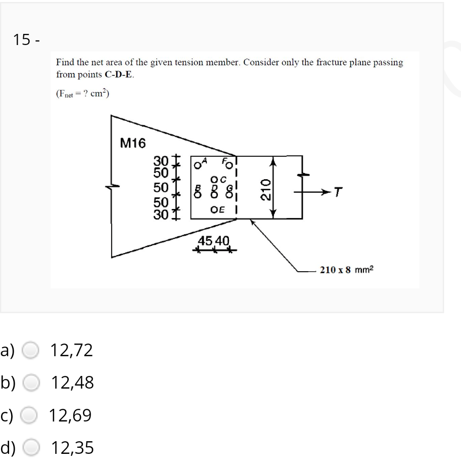
Find the net area of the given tension member. Consider only the fracture plane passing from points C-D-E. (Fnet = ? cm²) M16 30 50 OC 50 8 8 8 50 301 OE I 45,40 210 x 8 mm2 210


Q: The lap joint shown in Figure 4.2 is fastened by four 3/4 inch-diameter rivets. Calculate the…
A:
Q: 5 kN 2 m C E. A 6 kN 8 kN 2 m 2 m 2 m
A:
Q: Analyze completely and summarize results from joints to E 24 KN 1.2 m 0,6m D 1.5 m 12 K 0.3m B
A: To find reaction at all points of given frame
Q: The cross-section of the two wooden members is a rectangle with a = 120 mm and b = 60. They are…
A:
Q: 10/10 find the tensile stress in upper plate in section 3-3 80 kN 80 kN 8-bolt DIA. 10 MM 80 kN 80…
A: Given, P =80 kN diameter of bolts = 10mm thickness of plate(t)=8mm, width of plate (b)=300 mm
Q: Calculate the stresses in members AB, AC, and BC if the cross-sectional area of each member is 1200…
A: in ∆ABCsinθ=35 and cosθ=45where,θ=angle made by the member AC with the verticalthen from…
Q: Link AB is to be made of a steel for which the normal stress is 310 MPa. Determine the…
A:
Q: Given the clevis shown, P=25KN. If the shearing stress is limited to 60 MPa, what is the diameter of…
A:
Q: Q1:If allowable stresses are o, 165MPa, o, 100MPa T 70MPa determine max. value of W. W 300mm Ti00mm…
A: beam is given with uniformly distributed load and it has been asked to find the max value of that…
Q: 5 beam with the 75 mm wide flange at the bottom. Determine the moment of resistance of the section…
A: To determine the moment of resistance for given permissible stresses in tension and compression.…
Q: 1. The section shown in the figure fails in flexure. Determine the magnitude of the compressive…
A: Given Data: a = 8 in, b = 16 in, h = 28 in Dia of hole = 8 in f`c = 5 ksi and fy = 60 ksi To find :…
Q: On the figure below, determine the following: 1. Maximum bearing stress at joints ( bolts and…
A:
Q: Q1: Find the normal stresses at sections A-A, B-B, C-C, and, D-D for the body as shown in figure…
A:
Q: Q1: A circular steel rod ABCD is loaded as shown below. Use the following data to Find the maximum…
A: Given that: E = 200 GPa
Q: Two forces, each of magnitude P, are applied to the wrench. The diameter of the steel shaft AB is…
A: Calculate the value of P using both shear stress criteria and angle of twist criteria. The criteria…
Q: Situation 1- For the pin connection shown in Figure S56-021, the allowable shearing stress in the…
A:
Q: AP 35° 35°
A:
Q: 180 160 140 120 100 80 riator stress q (kPa)
A:
Q: Part A The corners of the square plate are given the displacements indicated with di = 0.40 in. and…
A: Given:- The displacements of the corners of the square plates are:- d1 = 0.40 in d2 = 0.64 in To…
Q: 5. The lap joint shown is fastened by two %-in.- diameter rivets. Calculate the maximum safe load P…
A: (As per student demand, Solution to 5 ) To find:Calculate the maximum safe load P
Q: 150 kN El is constant 3m 60° 200 kN 2 panels at 4m 8m
A: Method of joints: Method of joints is one of the methods which is used to solve unknown forces…
Q: Given the clevis shown, P=D25KN. If the shearing stress is limited to 60 MPa, what is the diameter…
A:
Q: For the Pratt bridge truss and loading shown, determine the average normal stress in member BE,…
A: Given data in question Truss Loads Span member length To find out Stress in member BE Note We…
Q: The rivet group connects two narrow lengths of plate, one of which carries a 15 kN load. I the…
A: According to the question two plate's of narrow length are connected to each other through rivets.…
Q: 3. The plate as shown weighing 30 kN is raised by a cable sling. The cable sling has identical…
A: To determine the shear stress in the pins. Given, Weight of the plate (W) = 30 kN Diameter of the…
Q: °. If the average shear stress in the pin may not exceed MPa, the bearing stress in the bell crank…
A: To find the minimum diameter of pin (d)-
Q: determine the maximum out P that can apply to the joint shown in fig. P2.30. bolt shear stress must…
A:
Q: 3. The lower ends of the 3 bars in the figure are at the same level before the rigid homogenous 18MG…
A:
Q: A thin triangular plate PQR forms a right angle at point Q. During deformation, point Q moves to the…
A: Determine the shear strain y at corner Q' after deformation.
Q: A wooden beam is fabricated by bolting together three members. The cross-sectional dimensions are…
A: Given: Diameter of bolt=7 mm Area of bolt A=π4×72=38.484 mm2 Spacing of bolts s=100 mm Shear force…
Q: 1. Using Method of Joints, Determine the Internal Force for each member as shown in the figure. 2.…
A: in above question is asked for calcuating memeber forces with method of joints and section. first…
Q: The axial load 396 kN applied to the lap joint is distributed equally among the three…
A: Answer We are given Axial load = 396 KN bolt diameter = 20.6 mm bolts width of plate w = 135.4 mm…
Q: (d) Consider nail B that connects the bottom flange to the beam web. If the nails used at B can…
A: Solution Given Data b1=11 ind1= 2.1 inb2= 2.1 ind2=10 inb3= 6 ind3=2.1 in
Q: Determine the deformation ( in inches) of the steel rod shown under the given loads if P = 68145 IbQ…
A:
Q: Determine the deformation of the steel rod (inches) in the figure shown under the given loads Given:…
A:
Q: The short steel post as shown in Figure 4 is a 152 x 152 UC37 with three compressive loads applied…
A: Stress on the face AB = Axial Compressive stress by three loads + Bending Compressive stress by load…
Q: 1.5-2 The strain in member AB was measured to be 8.9 x 10⁴. If the member is an L3 × 2 x ¼ of A36…
A: The strain change in length of the member AB can be a simple strain formula i.e, change in length to…
Q: 1. Using Method of Joints, Determine the Internal Force for each member as shown in the figure. 2.…
A: Using Method of Joints, Determine the Internal Force for each member as shown in the figure. 2.…
Q: 5. A steel punch can be worked to a compressive stress of 800 MPa. Find the least diameter of hole…
A:
Q: The member is to be made from a steel plate that is 0.25 in. 0.25 in. thick. If a l-in. hole is…
A:
Q: Q5: Calculate the following parameters for the section shown in figure(3) to resist moment 45 kN.m,…
A:
Q: 1. An angular section 120mm x 120mm x 10mm is riveted by a 22mm diameter rivets arranged as shown.…
A: As in the question figure rivet are staggered by 60mm, also rivets are present in both connected and…
Q: PROBLEM No. 2 The rigid bar ABCD of negligible weight is initially horizontal, and the steel rods…
A: E=29*106 psi to find displacement at Aand C
Q: Q3: For the body shown in figure (2). Determine the normal stresses at sections A-A, B-B, C-C, and…
A:
Q: Q.3.3 Please find the maximum normal stress in the steel rod ABCD as loaded. The diameter for…
A:
Q: 75 mm
A: Solution Given Data P1= 40 kNP2= 30 kNSteel type W310×74
Q: 4. The allowable bearing stress for the material under support A is 2 MPa. Determine the size of…
A: This is simply supported BeamTo find the Reaction at A & Bmoment about B = 0 , ΣMB= 0Ra x (AB)…
Q: A single unequal angle 100 x 75 x 6 is connected to a 10 mm thick gusset plate at the ends with six…
A: Given data, For a single unequal angle 100x75 is connected to a 10 mm thick gusset plate at the ends…
Q: 3. Two wooden members of 5.5" x 3.5" rectangular cross-section are joined as shown below (along the…
A: Given : Size of wooden members - 5.5"X 3.5" The max. allowable stress in the joint is 100psi in…
Q: The cross-section of the two wooden members is a rectangle with a = 120 mm and b= 60. They are…
A: The given values are as follows,a=120mmb=60P=9kN(a) α=30°(b)α=45°To Determine,The normal and shear…

Step by step
Solved in 2 steps with 1 images


- The vertical member shown in Figure STCN17.02 consist of two angles welded to the 8-mm thick gusset plate. Given the following data: Angle size: 75 mm x 50 mm x 6 mm (long legs back-to-back) Area of one angle = 738 mm Size of weld = 6 mm Yield strength of steel, Fy = 248 MPa Allowable weld shear stress, F, = 124 MPa a = 25 mm a. Determine the safe capacity of the vertical member in kN. b. If P= 185 kN, determine the length of weld L2 (mm) such that each weld have equal shear stress. Neglect end returns. c. If L1 = 140 mm and L2 = 70 mm, determine the safe load P (kN) based on weld capacity assuming all welds have equal stress. AP L1 L2Question-03: The steel tie bar shown in Figure 2 is to be designed to carry a tensile force of magnitude P = 30 kips whenbolted between double brackets at A and B. the bar will be fabricated from 0.6inches thick plate. Forthe grade of steel to be used, the maximum allowable stresses are: Normal stress = σn = 25 ksi, Bearingstress = σb = 55 ksi and Shearing stress = τ = 5.4ksi. Solve for the values of (a) the diameter d of thebolt, (b) the dimension b at each end of the bar and (c) the dimension h of the bar.Compute the nominal shear strength of an M107.5 of A572 Grad 65 steel.
- The axial load 396 kN applied to the lap joint is distributed equally among the three 20.6-mm-diameter rivets. What is the maximum tensile stress (in MPa) in the plate if w = 135.4mm and t = 27.1mm? Round off the final answer to three decimal places.The angle bracket shown, 75 mm x 75 mm x 15 mm thick, is 200 mm long. It is connected to the 16 mm thick flange of the column support with 2 of 16 mm diameter bolts. The bracket is subjected to a load of 42 kN from beam A. Assume that the load is applied concentrically at the connection. 1. Determine the resulting bolt shear stress in MPa 2. Determine the resulting bolt shear stress in MPa 3. Determine the critical bolt shearing stress in MPaThe following solid aluminum bar (E = 10,000 ksi; α = 11.70E-06/F) is located between two fixed supports. Segment AB has a diameter of 3 inches and segment CB has a diameter of 2 inches. The load P is equal to 25 kip and the temperature increases by 50°F. Determine: a. The reactions at the supports. Answ: Cy = 17.938 kip (downward); Ay = 42.938 kip (upward). b. The deformation at point B. Answ: 2.693E-03 pulg. c. The stress in both segments. Anws: 5.709 ksi, 6.07 ksi.
- A steel bracket of solid circular crosssection is subjected to two loads, each of which isP = 4.5 kN at D (see figure). Let the dimension variablebe b = 240 mm.(a) Find the minimum permissible diameter dminof the bracket if the allowable normal stress is110 MPa.(b) Repeat part (a), including the weight ofthe bracket. The weight density of steel is77.0 kN/m3.b. Calculate "P" in KN considering tension failure on net area Two A36 16mm Thick Steel Plates Are Connected By Four Rivets With Fv=152 MPa As Shown. Given: Rivet Dia 20 mm x=100 mmA horizontal beam AD is supported by an inclined strut CB carries a load W = 2.4KN at the position shown. The strut which consists of one bar is connected to the beam by a bolt passing through the three bars meeting at joint C. BC is 75mm wide and 10mm thick strut while AD is 100mm wide by 10mm thick rigid bar. (a)What is the minimum required bolt diameter in at C if the allowable bolt shear is 68MPa? (b)Determine the stress in strut BC. (c)Determine the bolt stress at A if its diameter is 20mm.
- What is the minimum required bolt diameter (mm) at C ifthe allowable bolt shear stress is 68 Mpa.a. 9 mm c. 11 mmb. 10 mm d. 12 mm Determine the stress (Mpa) in strut BC.a. 5.6 MPa c. 3.2 MPab. 2.8 MPa d. 6.4 MPa Calculate the bolt stress (Mpa) at A if its diameter is 20mm.a. 7.64 MPa c.11.46 MPab. 3.82 MPa d.14.92 MPaUse principles of steel solution. explain each step STEEL DESIGN Beam CD is simply supported at C and D. 1. Compute the maximum bending stress of beam CD. 2. By investigation, the beam CD has an allowable bending stress, Fb = 94MPa. To strengthen the beam, 2 cover plates of 10 mm thick are to beadded on the top and bottom flanges as shown in Figure ST - 903. 3. Compute the required width of the cover plates. 4. Compute the cut off point of the cover plates from each support at C and D.The steel tie bar shown in Figure 2 is to be designed to carry a tensile force of magnitude P = 30 kips whenbolted between double brackets at A and B. the bar will be fabricated from 0.5* ? inches thick plate. Forthe grade of steel to be used, the maximum allowable stresses are: Normal stress = σn = 25 ksi, Bearingstress = σb = 55 ksi and Shearing stress = τ = 4.5* ? ksi. Solve for the values of (a) the diameter d of thebolt, (b) the dimension b at each end of the bar and (c) the dimension h of the bar.