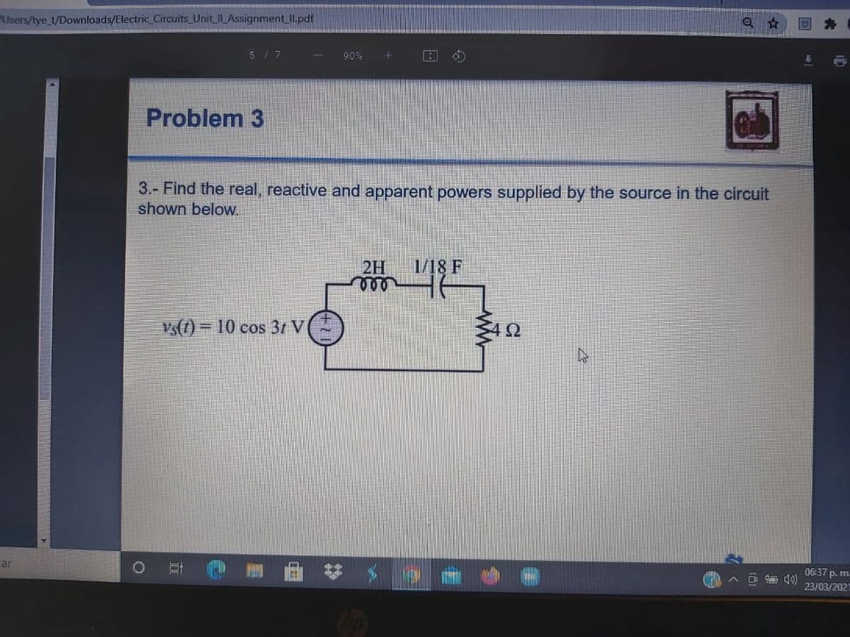
Find the real, reactive and apparent powers supplied by the source in the circuit shown below.


Q: use the circuit below find the current load using Maxwell mesh method
A:
Q: For the circuit shown below, determine the real, reactive and apparent power for each element…
A: Write KVL equation for the circuit given and solve for current I; 2402∠60°-I5+8j-2802∠30°=0…
Q: Vs(t)=12cos2500t V, Is(t)=0.5 cos(2500t-30) A. 50 4 mH 4 mH ll E80 F (140) 3102 ll
A: We will solve this problem using nodal analysis method. Both the Voltage and current source have…
Q: Find the value of RL for max power transfer to RL in the circuit shown below, and calculate the…
A: In this question we need to find a value of load resistance so that maximum power is transferred to…
Q: 2- Calculate the effective, reactance and apparent capacities provided by the circuit source shown…
A:
Q: (a) Calculate real power, reactive power and apparent power dissipated by each component (resistor,…
A:
Q: In the circuit shown below, load A receives S, =80+ j40 VA, while load B absorbs S, =100– j200 VA.…
A: The given circuit is shown below: It is given that: SA=80+j40 VASB=100-j200 VA
Q: Given a variable resistor R of unknown resistance connected in parallel with an inductive reactance…
A:
Q: Given voltage source = 100V∠0°, give the value of real power, apparent power, and reactive power…
A:
Q: 1. Answer the following questions from the circuit below. I Z=3+j4 Q z, = 6+j8 N |Z, = 3-j2 Q %3D v…
A: Given circuit shown
Q: The input to the circuit shown in the figure is the current i(t)=120 cos(4000t) mA Determine the…
A: In the beginning step first of all we should convert all the capacitor and inductors in to the there…
Q: The circuit depicted below, has beem in operation for a very long time. Please find the power…
A: Solution From the given diagram,…
Q: For the circuit shown, what is the complex power, S, average power, Pay, and reactive power, Q,…
A:
Q: Use the definition of complex power to calculate the real and reactive power for the load of the…
A: It is given that: Vs=110∠0 V;Rs=4Ω;RL=10Ωand jXL=j6Ω
Q: Determine the apparent power and the power factor if a series-connected load has current, i(t) = 5…
A: Apparent power = VI* where V and I are rms value. Impedance = V / I.
Q: For the circuit shown in Figure below, find the complex power absorbed by Z1, Z2, Z3, and the…
A:
Q: 5. Which components' powers are positive? Whať's the meaning of positive power?
A: For The load components like light load(resistor),motor(inductive load) etc the power is positive…
Q: Q2: For the circuit shown below, determine the apparent power delivered by the source, power…
A:
Q: For the circuit shown in Figure below, find the complex power absorbed by Z1, Z2, Z3, and the…
A: complex power = S = P+JQ = VI* Where P= Real Power Q= reactive power V =…
Q: 2 Ω 15 mH + 500 με 4 V₁ E20 mH 5 Ω >0.5V,
A: Given circuit Also given 400 Vrms source is connected across the load , then the real and reactive…
Q: Can you apply superposition theorem on the power? Why?
A:
Q: Given the circuit below and the associated set of voltages and currents, the real Power developed by…
A:
Q: 1. Explain maximum power transfer theorem 2. What are some of the instances where power transfer is…
A: The summary of loads in maximum power transfer theorem Here prefix L is for loads. And…
Q: 14. An inductive coil and a non-inductive resistance R ohms are connected in series across an a.c.…
A: Given the inductive coil and non- inductive resistance R are connected The inductive coil consists…
Q: In the circuit shown below, load A receives S, =80+ j40 VA, while load B absorbs S, =100– j200 VA.…
A:
Q: 2. Find the current i,, iz and iz in the circuit below: 1852 35
A: In this question we need to find a unknown current shown in the circuit.
Q: In the power triangle of figures below, calculate the missing parameters; the reactive power (Q),…
A:
Q: Q2. For the circuit shown in Figure Q2, (a) find the source's power factor and the total current…
A: The solution is given below
Q: If the apparent power of a source is known, then the power factor, active and reactive powers can be…
A: Resistors, inductors and capacitors form an integral part of any electrical circuit. A source,…
Q: Q4. The source current in the circuit shown is in Figure 3 a) What impedance should be connected…
A: Solution: Assuming the source current as 10 A with the frequency as 50 Hz.…
Q: For the circuit shown below, R 2 2, L= 20 mH, and E= 100v. TH source is 120 V rms at 60 Hz. (a)…
A: We are authorized to answer three subparts at a time, since you have not mentioned which part you…
Q: Problem 3 Use the definition of complex power to calculate the real and reactive power for the load…
A: Given circuit shown Vs=110∠0° vRs=4 ΩRL=10 ΩjXL=j6 Ω
Q: The swing equation provides the information about Stability of the system Efficiency of the…
A: In this question , we have to write about swing equation importance .
Q: Search the mesh current method to find the steady state expression for the branch currents i, and i,…
A: Solution- Given, Va = 50sin106tVb = 25cos106t+90°Va = 50sin106t = 50 cos106t-90° = -50j…
Q: max. ave. power transfer
A:
Q: R1 XL 5Ω R3 a ll ll 6Ω 8 2 120 + + R21 E 10 V Z 0° E2 20 V Z 30° a' Thévenin
A: Thevenin's Theorem states that “Any linear two terminal circuit containing several voltages and…
Q: 15.(i). A resistance of 50 N, an inductance of 0.1 H, and a capacitance of 30 mf are connected in…
A: As per our company guidelines we are supposed to answer only first 3 subpart kindly repost other…
Q: A dc transmission facility is modeled by the approximate series circuit shown below. If the load…
A:
Q: In the circuit shown below, find the complex power supplied by the source and the source power…
A: In given circuit three loads are connected in parallel. Voltage will be same across each load but…
Q: Find the power delivered to an element whose current is given as i = 5 cos 60at A and voltage at v =…
A:
Q: Two circuits, the impedances of which are given by Z, = 15 + jl2 ohms and Z. - 8 - j5 ohms are…
A:
Q: 2.Calculate the real power taken by each impedance and voltage source in the circuit below.Show that…
A:
Q: Given a mesh connected system with reactive factor of 60 percent and true power of 2,500 kW.…
A: We need to find out reactive power
Q: Example 7: Find the power delivered to the d.c. motor of figure shown if the voltage applied is 120…
A: DC motor: It is an electrical device that converts electrical energy to useful mechanical energy.
Q: Given a total voltage in a circuit with vT (t) = 250 sin (wt + 25°) V . If a voltage drop of element…
A:
Q: Given the circuit below and the associated set of voltages and currents, the real Power delivered by…
A:
Q: Discuss the whole system of primary power distribution
A: Distribution system mean the electrical power convert low voltage to high voltage at generating…
Q: Consider the system shown. E is a standard 120 V input. If the three loads are 45 W, 60 W and 75 W…
A: Given data, There are three loads which take 45 W, 60 W and75 W. E is a standard input voltage…
Q: In Transformers: a. What is the relationship between the turns ratio and the primary to secondary…
A:
Q: Consider the below circuit. Suppose that Vrms = 700 V and R = 30 Ω. 1- Find the power delivered by…
A:
Find the real, reactive and apparent powers supplied by the source in the circuit shown below.

Step by step
Solved in 2 steps with 1 images


- B.1. Attenuation is measured inA. parts per million (ppm).B. watts (W).C. decibels (dB).D. amperes (A). B,2. While you're wiring portions of a structured cabling system, you add a conductor termination thatautomatically removes the insulation from the conductor as it's seated into the connector. Which of thefollowing connection techniques did you use?A. Fiber optic terminationB. CleavingC. Plug-compatible connectionD. Insulation displacement connectionB.C. Which of the following is a specialty electrical wiring system that's used in patient care areas of healthcare facilities to provide added protection against the possibility of electrical shock?A. An isolated power systemB. An intrinsically safe circuit systemC. A redundant grounding systemD. An automatic transfer switching systemAirframe Electrical system Question: State the four common aircraft system voltages. (Source: FAA AC 43.13-1B/2B)Given a 400sq.m single family dwelling unit to be provided with 230V, 1-phase, 2-wire be service, andhaving the following loads: 2-1.5hp A/C, 2-1.0hp A/C, 1-0.5hp water pump, 4-800W water heater, 2-6kWelectric range and 2-1kW microwave oven, determine a) the total connected load, b) the total demand load,c) the overall %demand factor, d) the size of THW feeder conductor, ground wire and IMC conduit, e) therating of feeder overcurrent protection using inverse time circuit breaker
- . If a 100 MW coal-fired power plant is replaced by a natural gas plant, what are the before and after annual emissions of: Sulfur dioxide NOx Carbon dioxide https://www.eia.gov/todayinenergy/detail.php?id=44095# (Links para um site externo)In a string of three identical suspension insulator units supporting transmission line conductor.if the self capacitance of each unit is debited as C farads, The capacitance of each connector pin to ground can be taken as 0.1C farad's. If the maximum permissible voltage per unit is given as 20 kva then calculate A.maximum safe working voltage B.string efficiencyAn impedance coil is connected in series with a fixed resistor, and a 120-V, 50-cyclesource is then impressed across the combination. If the voltage drops across the coil andthe fixed resistor are 70 and 80 V, respectively, when the circuit current is 1.4 A, calculatethe resistance and inductance of the impedance coil. PLEASE ANSWER ASAP
- DEGREE: ELECTRICAL ENGINEERING SUBJECT/COURSE: AC CIRCUITS NOTE: Please solve in this way. 1. Please have a good handwriting, some of the answers are not readable. Thank you! 2. GIVEN.(include symbols and units) 3. REQUIRED/FIND/MISSING (with symbol/s) 4. ILLUSTRATION (Required). 5. STEP-by-STEP SOLUTION with Formulas and Symbols. No Shortcut, No skipping, and detailed as possible 6. FINAL ANSWERS must be rounded up to three decimal places PROBLEM: • A 4200 V, three-phase transmission line has an impedance of 4+j1 Ω per phase. If it supplies a load of 1MVA at 0.75 power factor lagging. Find: a. The complex power b. The powerloss in the line c. The voltage at the sending endIf the values of real power and reactive power is specified for a bus, then it is called as PV bus. Select one: True FalseThe data for a wind turbine is given below: Wind speed = 14 meters/sec, Length of blade = 10 meter Refer to the above wind turbine choose the correct statement a. The wind rotor swept area is 40square meters. b. The wind rotor swept area is 314 square meters. c. The wind rotor swept area is 31.4 square meters. d. The wind rotor swept area is 62.4 square meters.
- A 210V, 50 Hz, single phase radial distribution system, the resistance of the wire is 0.0008 ohm/m supply and return. Two loads are connected and it consumes 10 and 10 A respectively and are fed from the cable at distance of 15 and 15 respectively. Calculate the voltage available across load 1 and 2A 3-phase transmission line is being supported by three-disc insulators. The potentials across top unit (i.e. near to the tower) and middle unit are 8 KV and 11 KV respectively. Calculate: 1) The ratio of capacitance between pin and earth to the self-capacitance of each unit 2) The line voltage 3) String efficiency Subject Power Transmission And Distributionplease explain steps-by-steps solution tq