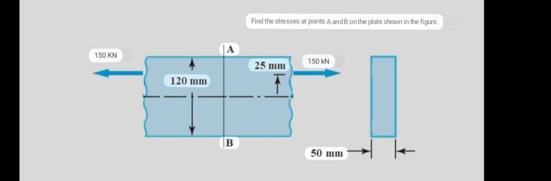
Find the stresses at points A and B on the plate shown in the figure.


Q: Q2) For the problem shown in the figure, - Find the axial displacement at the end B - Determine the…
A: for solution refer below images.
Q: Find the stresses at points A andB on the plate shown in the figure.
A: The normal stress at the points A and B can be determined as,
Q: Question 3) Plane stress state at a point is given in the figure. a) Calculate the principal…
A: τxy=10 Mpaσ1,2=σx+σy2±σx-σy22+τxy2 As it is case of pure shear so σx=0 and σy=0…
Q: F1. The rigid bar ABC in the figure is supported by a clevis and pin at its right hand side and by…
A: Draw the free-body diagram of the beam.
Q: 450 kN and 100 kN forces were applied to the recessed beam shown in the figure. Find the stresses at…
A:
Q: The young modulus of the bar, which is made of St70 steel material shown in the figure, is 210GP..…
A: Given data as per the question Young modulus of the bar =210 Gpa cross section of the bar=500…
Q: Problem 6 For the structure shown in the figure, determine the normal and shear stresses at point A…
A: Given data: Vz=6 kN Need to determine the normal and shear stresses at point A on the cross section…
Q: For a closed end cylinder where the inner radius is 20 mm and outer radius is 40 mm, and the…
A: Sddd
Q: Q.3) For the shaft consist of two parts shown in figure. If shaft (1) has outside diameter doutl =…
A:
Q: Determine the torsional stress of the cantilever shafts show in the figure below:
A: Outer diameter, d1=20 mm=0.02 mInner diameter, d2=15 mm =0.015 mTorque, T=5 kN.mLength, L=200 mm=0.2…
Q: as given below 80 mm a) Normal and shear stresses occurring at point A Find and show it on the plane…
A: Given: The diameter of the shaft, d = 20 mm = 0.02 m
Q: S A- Sección 4-a 1200 N B 1500 N 1000 N
A:
Q: b) For the thin walled pressure vessel subjected to an internal pressure of 150 psi and as shown…
A: Given Data Internal pressure of vessel is: P=150 psi The length of the vessel is : L ft Thickness…
Q: shear stress in t
A: Given data sigma x = -100 MPa sigma y = 0 sigma xy = 0 required normal stress at 300 shear stress…
Q: 3. An element in a strained body is subjected to a tensile stress of 100 MPa and a shear stress of…
A: When an amount of force act on an object, then the force has the tendency to change the shape of the…
Q: - : The forces as given below are applied as shown in the figure. F:=10 kN, F;=5 kN and F3=3 kN. The…
A: Given F1 = 10 kN F2 = 5 kN F3 = 3 kN To find Stress at point D Shear stress Principal stresses
Q: Find the minimum principal stress for the stress case given in the figure.
A:
Q: 8 ksi 4 ksi 12 ksi
A: From the given figrue, σx = -12 ksi σy = -8 ksi τxy = 4 ksi
Q: C ):- Draw the Mohr's Circle of the stress element shown in figure. Find:- 1) principle stresses. 2)…
A:
Q: A solid steel bar with a diameter of 50 mm is subjected to three forces as shown in the figure,…
A: In the given problem, the main stresses will be developed at point B due to 1200N force which will…
Q: Find the maximum shear stress for the stress case given in the figure.
A: Given Data The stress acting in x direction is: σx=100 MPa The stress acting in y direction is:…
Q: Two forces, 100 kN and 200 kN, act on the rectangular column in the figure. Find the stresses at A…
A: The cross-section of the rectangular column is shown below: considering dimensions in mm
Q: The force F=(...) kN exerted on the bar as shown in the figure. The bar's diameter is 150mm. Find…
A:
Q: The steel bar in the figure has a diameter of 60 mm. As the shaft is loaded with the CDE rigid arm…
A: Given: Diameter of the steel bar is 60 mm. The loaded shaft is shown below:
Q: Qr) Find the stress distribution at the section ABCD for the block shown in the figure. Sketch the…
A:
Q: It has an L arm exposed to P load as shown in the figure on the side. Calculate the stresses that…
A: Consider the diagram shown below for the given arm.
Q: For the figure shown below. Calculate the increase in vertical stresses (Ac) at point A at depth of…
A:
Q: A circular bracket with a diameter of 100 mm is fixed to a wall as shown in the figure below.…
A:
Q: A torque and two forces seen in the figure are applied. the diameter is 65mm. Determine the…
A:
Q: ABCD rigid rod is supported as shown in the figure. 40 degrees increase in temperature in the case…
A: Given data, Increase in temperature, ∆T = 40° α1 = Thermal expansion of rod 1 = 16.9×10⁻⁶/°C α2 =…
Q: When there is a plane stress condition as shown in the figure, display this stress in the form of…
A:
Q: The foundation bolt is shown in the below figure a force F = 300 N. The bolt material is wire of…
A:
Q: Problem 6 For the structure shown in the figure, determine the normal and shear stresses at point A…
A:
Q: A circular bracket with a diameter of 100 mm is fixed to a wall as shown in the figure. Determine…
A:
Q: The force F=(....) kN exerted on the bar as shown in the figure. The bar's diameter is 150mm. Find…
A:
Q: (320) mm inside diameter and (64) mm thickness is subjected to an internal pressure of 15 MPa. Find…
A:
Q: Question 3) Plane stress state ata point is given in the figure. L. a) Calculate the principal…
A: τxy=10 MPaσ1,2=σx+σy2±σx-σy22+τxy2 Since it is case of pure shear so σx=0 &…
Q: An element in plane stress from the fuselage of an airplane is subjected to compressive stresses of…
A: To find: The σy1 acting on an element oriented at a clockwise angle of 40° from the horizontal.…
Q: A circular bracket with a diameter of 100 mm is fixed to a wall as shown in the figure below.…
A:
Q: A circular bracket with a diameter of 100 mm is fixed to a wall as shown in the figure. Determine…
A:
Q: Question: Find schematically the normal and shear stresses in the plane when the element in the…
A:
Q: For the hollow built-in pipe with an inner diameter of 48 mm and an outer diameter of 60 mm, the…
A:
Q: a. Calculate the largest tensile and compressive stresses that occur in section a-a shown in the…
A:
Q: Find the maximum shear stress at a plane if the major and minor principal stresses at a point are 3…
A:
Q: b) For the thin walled pressure vessel subjected to an internal pressure of 150 psi and a shown…
A: Permissible stress is stress which produces due to pressure or forces which does not exceed the…
Q: Find the maximum principal stress for the stress case given in the figure
A:
Q: 150 kN A 500 mm ISOKN T=50 kN.m
A: Solutions: Moment of inertia of the rod=π×d464=π×0.04464=1.2566×10⁻⁷m4 Bending moment at…
Q: (3): A steel bar ABCD (4m) long is subjected to forees as shown in Figure. Find the stresses in each…
A: given:

Step by step
Solved in 3 steps with 3 images


- .4 The stresses on an clement arc known to be sx= 120 MPa, sy= 100 MPa, and txy= 75 MPa. Find the stresses on an inclined section through the element at an angle ? = 45°.‘7.3-11 The stresses on an element are sx= -300 psi and sy= 600 psi. Find the maximum shear stresses on the element and show them on a sketch of a properly oriented clement.Solve the preceding problem if the norm al and shear stresses acting on the element are sx = 2100 kPa, sy= 300 kPa, and txy= -560 kPa, and the seam is oriented at an angle of 22.5° to the clement.
- -26 A rectangular plate of dimensions 125 mm × 75 mm is subjected to tensile stress sy= 67 kPa and compressive stress a. If it is known that the normal stress along the diagonal t—t is ??t= -6.57 kPa, find stress ??y on element A. aThe state of stress on an element of material is shown in the figure. Calculate the unit volume change of the element if the stresses x and y. are -20 ksi and 10 ksi, respectively. Assume E = 10,600 ksi and v = 0.33.The stresses at a point on the down tube of a bicycle frame are trx= 4800 psi and t = -1950 psi (see figure). It is known that one of the principal stresses equals 6375 psi in tension, (a) Determine the stress (b) Determine the other principal stress and the orientation of the principal planes, then show the principal stresses on a sketch of a properly oriented clement.
- The hollow drill pipe for an oil well (sec figure) is 6,2 in. in outer diameter and 0.75 in. in thickness. Just above the bit, the compressive force in the pipe (due to the weight of the pipe) is 62 kips and the torque (due to drilling) is 185 kip-in. Determine the maximum tensile, compressive, and shear stresses in the drill pipe.-18 through 7.3-22 An element in plane stress (see figure) is subjected to stresses o, a., and (a) Determine the principal stresses and show them on a sketch of a properly oriented element. (b) Determine the maximum shear stresses and associated normal stresses and show them on a sketch of a properly oriented element. 7.3-18 a=2I50kPa, ay=375kPa.Txy.=-460kPa• - 7.4-7 An element on the surface of a drive shaft is in pure shear and is subjected to stresses ??xy= 2700 psi, as shown in the figure. Using Mohr’s circle, determine the following. (a) The stresses acting on an element oriented at a counterclockwise angle ?= 52° from the y axis. (b) The principal stresses. Show all results on sketches of properly oriented elements.
- The polyethylene liner of a settling pond is subjected to stresses ax= 350 psi. a = 112 psi. and = -120 psi, as shown by the plalte-stress element in the figure part a. Determine the normal and shear stresses acting on a seam oriented at an angle 01300 to the element, as shown in the figure part b. Show these stresses on a sketch of an element having its sides parallel and perpendicular to the seam.At a point on the surface of an elliptical exercise machine, the material is in biaxial stress with t = 1400 psi and trv = —900 psi, as shown in the figure part a. The figure part b shows an inclined plane aa cut through the same point in the material but oriented at an angle ft Determine the value of the angle 6 between zero and 90° such that no normal stress acts on plane aa. Sketch a stress clement having plane aa as one of its sides and show all stresses acting on the clementSolve the preceding problem if the normal and shear stresses acting on element B are 56 MPa, 17 MPa, and 27 MPa (in the directions shown in the figure) and the angle is 40° (clockwise).