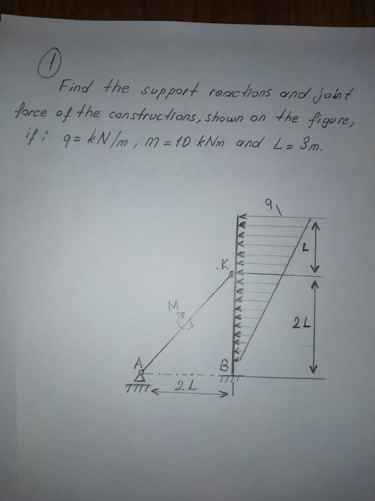
Find the support reactions and joh brce of the constructions, shown on the fi gu. 7: 9= kN m, m = 10 kNm and L= 3m, %3D


Q: Q- 3. For the given structure below; considering W = 120N &L= 120 cm; a. Draw the Free Body Diagram…
A:
Q: P (kN) 2 (kN/m) 1kN/m (a) m 1m
A:
Q: On a structural steel I profile beam a distributed load and M moment is applied as shown in the…
A: Given data On a structural steel I profile beam a distributed load and M moment is applied as shown…
Q: _Is4lhVkfYEXQZh-UZqdpqqMbGT. 1/ 2 100% 1) For beam shown below, find reaction forces in supports A &…
A:
Q: A box is produced by joining the wooden and plywood rectangular elements with screws as shown in the…
A:
Q: A beam system ABC is freely supported in A and C and evenly loaded with q from A to B. In addition,…
A: We have given A beam system ABC is freely supported in A and C and evenly loaded with q from A to B.…
Q: olve carefully, include the units in every step and draw the diagram. Thanks! In a 2.5 m…
A:
Q: The shape of the beam made of U profile ensures safe loading. Find the length c of the overhangs so…
A:
Q: The cross section of an extorior column is aT beam with the following cross sectional intomation bf=…
A: Given: The width of flange, bf = 1900 mm The thickness of the flange, hf = 50 mm The width of the…
Q: For the beam shown, determine the support reactions using singularity functions and procedure 1 from…
A: he support reactions using singularity functions
Q: Q-5 Find the maximum tensile and compressive flexure stresses for the cantilever beam shown in fig…
A: Given Data The uniform distributed load acting on the beam is: W=4 kN/m The Length of the beam is:…
Q: B Support reactions will be found in the gerber beam whose loading condition is given in the figure.…
A:
Q: 36mmø CISE NO. 1 (REACTIONS) 50deg C A Support 6m 4m 5 RA 12 1. Compute the stress in the support at…
A: Given: The value of force is W=107 kN. The diameter of wire is d=36 mm. Determine the equation for…
Q: The beam W24x104 beam is constructed of A-36 steel. AC has a cross-sectional area of 1 square inch…
A: For W24×104,I=3100 in4For A-36 steel,E=210 GPa=3.046×10⁷ lb/in2, The deflection due to the UDL of…
Q: 700N M-150UNm 2m 3m For the above dlagram, given that F, - 450 N. 0-45 degrees and d-5 m calculate…
A:
Q: Consider an 8-m long simply supported T-beam with overhangs loaded as sh w kN/m D kN-m 50 kN-m A B D
A:
Q: 1 A 250 mm x 125 mm I-beam having I, 3717-8 W V, y 30° U, x cm² and Iy = 193-4 cm4 is used as a…
A: A 250 mm×125 mm I-beam with Ix=3717.8 cm4 and Iy=193,3 cm4 is utilised as a purlin on a roof truss…
Q: Find the bending stvess at point B located at stress at Im from the right end of the beam. 2 Nlm…
A: Given:
Q: A simply supported hollow cylinder beam is subjected to a uniform load w of 2700 N/m, and an inner…
A: Simply supported beamω=2700 N/m;=2700×10-3N/mmP=450 kpa;ro=47 mm ri=45 mm; L=4m,
Q: A simply supported beam with a cross-section as shown in Fig. 1.19 spans 15 m and carries a total…
A:
Q: 2 m C 30° 2 m 10 kN A D I I Determine the classification of the truss shown in the figure
A:
Q: Draw (FBD) and calculate the support reactions in the simply support beam ABCD below 3kN 5kN bo 60°…
A:
Q: Question 4 a. A solid circular L shaped ABC structure is built in at one end and is point loaded at…
A:
Q: Q2// B) For the simply supported T-beam shown in Fig. (3), check the adequacy of the cross-section…
A: Given, A T section. Yield stress Fy = 400 Mpa. Total load acting on the beam , WL + Wd = W =…
Q: (a) In Fig. a6.00-m-long, uniform beam is hangingfrom a point 1.00 m to the rightof its center. The…
A: Given Data: The weight of the beam is W1 = 140 N. The weight hanging at the top is W2 = 100 N. The…
Q: Figure Y shows a rigid body consisting of beam ABC loaded with a 500 Nm moment, a box with a weight…
A: Given Data, Moment, M = 500 Nm(clockwise) Weight of the box,W = 600 N Mass of the tyre, m= 10 Kg To…
Q: 2. On the given truss belou find the unknown reactions such as Ri, Rz and R3 tz=500 KN Lg=400KN…
A: Use equilibrium equations to solve the given problem. Equilibrium equations: +→∑FX=0+↑∑FY=0+↺∑Mat a…
Q: Figure below shows a simply supported uniform beam supports a 40 kN load. Determine the reactions R.…
A: for solution refer below images.
Q: A propped cantilever beam has flexural rigidity EI = 2.5 MN•m2. When the loads shown are applied to…
A:
Q: (TT B H L Data Input • A distributed load p = 4.4 t/m, with L = 11 m and H = 7 m, acts on a…
A: Three hinged arc A three-hinged arch is geometrically unchangeable statically determinate structure…
Q: Installed appointment of a beam made of a U profile in the figure Find the length c of the overhangs…
A: FBD of given fig. Finding reactionRA+RB=30+30 +40×6RA+RB=300KnSo RA=RB=3002=150Kn
Q: Read the question carefully and give me right solution according to the question.. Please answer…
A:
Q: The beam shown below has a pin or hinge joint at B. The beam is simply supported at A. For this…
A: Step 1: Part A) Since Joint B is a hinged joint, therefore the internal moment is zero. Therefore…
Q: Wo = 14 kips/ft, wcD = 3.5 kips/ft, Lag = 7.0 ft, Lgc = 7.0 ft, LcD = 8.0 ft, LDE = 4 ft. %3D wo WCD…
A:
Q: A G Support reactions will be found in the gerber beam whose loading condition is given in the…
A:
Q: A 20'x30" column with A,= 6#6 and A, = 6#8. If the neutral axis depth= 7", concrete cover (d)= 2 in,…
A: There are two types of forces that are acting on a circular surface. One type of force is Radial…
Q: 1.13 A couple M of magnitude 1500 N m is applied to the crank of an engine. For the position shown,…
A: wall reaction is considered only on one side in the calculation.
Q: Example The beam ABC is loaded via a 500 N.m couple and a 600 N force as shown The beam is connected…
A:
Q: Example The beam ABC is loaded via a 500 N.m couple and a 600 N force as shown. The beam is…
A: Static equilibrium: A body is said to be in static equilibrium if it satisfies the following…
Q: USING MOMENT AREA METHOD, find reaction at support C in N. El is constant. 600 N/m A 2m 3m
A:
Q: Current Attempt in Progress Calculate the support reactions at A and B for the loaded beam. Assume…
A:
Q: A simply supported hollow cylinder beam is subjected to a uniform load w of 2700 N/m, and an inner…
A:
Q: A girder ABCDE bears on a wall for a length BC and is prevented from overturning by a holding-down…
A:
Q: 400 N Find reactions at supports C and B take beam AC wieght 20Kg Free Body Diagram F.B.D B = 2 m 1…
A:
Q: Q5/ A rectangle RC beam is reinforced with 5 Ø16mm in the tension zone as shown in Figure 4. Check…
A:
Q: Find reaction at C for a frame shown. using Consistent Deformations Method and Least Work Method 6 m…
A: Total Strain energy for the frame,U=Strain energy in semicircular portion+Strain energy in straight…
Q: P = 36 kips |A B C 9' - 6'-
A: A beam is defined as a structural member subjected to transverse shear load during its…
Q: Bonus problem) Analyze the following frame degrees of freedom. Find reactions and finally, ustant…
A: 1 Free BMDBMAB(Maximum)=WL4=12×124=36kip.ftBMBCMaximum=Wl28=3×1228=54kip.ft2Area of BMDFor span…
Q: Problem No. 3 Using double integration method to determine the deflection at L and 1.5L for the beam…
A:
Q: Find the supportive force system for the cantilever beam shown pinned at C. Given data: Point load,…
A: Consider the free body diagram: For Part CB:Cy+By=380+80*2Cy+By=540Taking moment about point…
can you please resolve the question?

Step by step
Solved in 2 steps with 3 images


- A steel riser pipe hangs from a drill rig located offshore in deep water (see figure). (a) What is the greatest length (meters) it can have without breaking if the pipe is suspended in the air and the ultimate strength (or breaking strength) is 550 MPa? (b) If the same riser pipe hangs from a drill rig at sea, what is the greatest length? (Obtain the weight densities of steel and sea water from Table M, Appendix I. Neglect the effect of buoyant foam casings on the pipe.).17 A mountain-bike rider going uphill applies torque T = Fd(F = l5lb, d = 4 in.) to the end of the handlebars ABCD by pulling on the handlebar extenders DE. Consider the right half of the handlebar assembly only (assume the bars are fixed at the fork at A). Segments AB and CD are prismatic with lengths L, = 2 in.andL3 = 8.5 in, and with outer diameters and thicknesses d01 = 1.25 in. 101 = 0.125 in. and d03 = O.87in.,i03 = 0.ll5in, respectively as shown. Segment BC’ of length L, = 1.2 in. however. is tapered, and outer diameter and thickness vary linearly between dimensions at B and C. Consider torsion effects only. Assume G = 4000 ksi is constant. Derive an integral expression for the angle of twist of half of the handlebar tube when it is subjected to torque T = Fd acting at the end. Evaluate ‘b1-, for the given numerical1ues.Space frame A BCD is clamped at A, except it is Free to translate in the .v direction. There is also a roller support at D, which is normal to line CDE. A triangularly distributed Force with peak intensity q0 = 75 N/m acts along AB in the positive - direction. Forces Px= 60 N and Pz = = 45 N are applied at joint C, and a concentrated moment My = 120 N . m acts at the mid-span of member BC. (a) Find reactions at supports A and I). (b) Find internal stress resultants N. E’I T, and .11 at the mid-height of segment AB.
- A foot bridge on a hiking trail is constructed using two timber logs each having a diameter d = 0.5 m (see figure a). The bridge is simply supported and has a length L = 4 m. The top of each log is trimmed to form the walking surface (see Fig, b)LA simplified model of the bridge is shown in Fig. g. Each log must carry its own weight w = 1.2 kN/m and the weight (P = 850 N) of a person at mid-span, (see Fig. b). Determine the maximum tensile and compressive stresses in the beam (Fig, b) due to bending. If load h is unchanged, find the maximum permissible value of load ... if the allowable normal stress in tension and compression is 2.5 M Pa.Solve the preceding problem using the fol low-data: W 8 × 21 section, L = 84 in., P = 4.5 kips, a = 22.5°.A steel post (E=30×106) having thickness t = 1/8 in. and height L = 72 in. support a stop sign (see figure), where s = 12.5 in. The height of the post L is measured from the base to the centroid of the sign. The stop sign is subjected to wind pressure p = 20 lb/ft2 normal to its surface. Assume that the post is fixed at its base. What is the resultant load on the sign? (Sec Appendix E, Case 25, for properties of an octagon, n =8.) What is the maximum bending stress in the post? Repeat part (b) if the circular cut-outs arc eliminated over the height of the post.
- Solve the preceding problem for the following data: b = 6 in., b = 10 in, L = 110 ft, tan a = 1/3, and q = 325 lb/ft..2 A ligmio.irc ii supported by two vorlical beams consistins: of thin-walled, tapered circular lubes (see ligure part at. for purposes of this analysis, each beam may be represented as a cantilever AB of length L = 8.0 m subjected to a lateral load P = 2.4 kN at the free end. The tubes have a constant thickness ; = 10.0 mm and average diameters dA = 90 mm and dB = 270 mm at ends A and B, re s pec lively. Because the thickness is small compared to the diameters, the moment of inerlia at any cross section may be obtained from the formula / = jrrf3;/8 (see Case 22, Appendix E); therefore, the section modulus mav be obtained from the formula S = trdhlA. (a) At what dislance A from the free end docs the maximum bending stress occur? What is the magnitude trllul of the maximum bending stress? What is the ratio of the maximum stress to the largest stress (b) Repeat part (a) if concentrated load P is applied upward at A and downward uniform load q {-x) = 2PIL is applied over the entire beam as shown in the figure part b What is the ratio of the maximum stress to the stress at the location of maximum moment?A sign of weight W is supported at its base by four bolls anchored in a concrete footing. Wind pressure P acts normal to the surface of the sign; the resultant of the uniform wind pressure is force fat the center of pressure (C.P). The wind force is assumed to create equal shear forces F/4 in the y direction at each boll (see figure parts a and c). The overturning effect of the wind force also causes an uplift force R at bolts A and C and a downward force (— R) al bolts B and D (see figure part b). The resulting effects of the wind and the associated ultimate stresses for each stress condition are normal stress in each boll (h — 60 ksi); shear through the base plate (th = 17 ksi); horizontal shear and bearing on each bolt ( tfur = 25 ksi and cr^ = 75 ksi): and bearing on the bottom washer at B (or D) (abor = 50 ksi).
- A large precast concrete panel for a warehouse is raised using two sets of cables at two lift lines, as shown in the figure part a. Cable 1 has a length L1 = 22 Ft, cable 2 has a length L2= 10 ft, and the distance along the panel between lift points Band D is d = 14 ft (see figure part b). The total weight of the panel is W = 85 kips. Assuming the cable lift Forces F at each lift line are about equal, use the simplified model of one half of the panel in figure part b to perform your analysis for the lift position shown. Find the required cross-sectional area AC of the cable if its breaking stress is 91 ksi and a factor of safety of 4 with respect to failure is desired.Find support reactions at 4 and Band then use the method of joints to find all member forces. Let b = 3 m and P = 80 kN.Find expressions for shear force V and moment M at v = L/2 of beam AB in structure (a). Express V and M in terms of peak load intensity q0and beam length variable L. Repeat for structure (b) but find Fand M at m id-span of member BC.