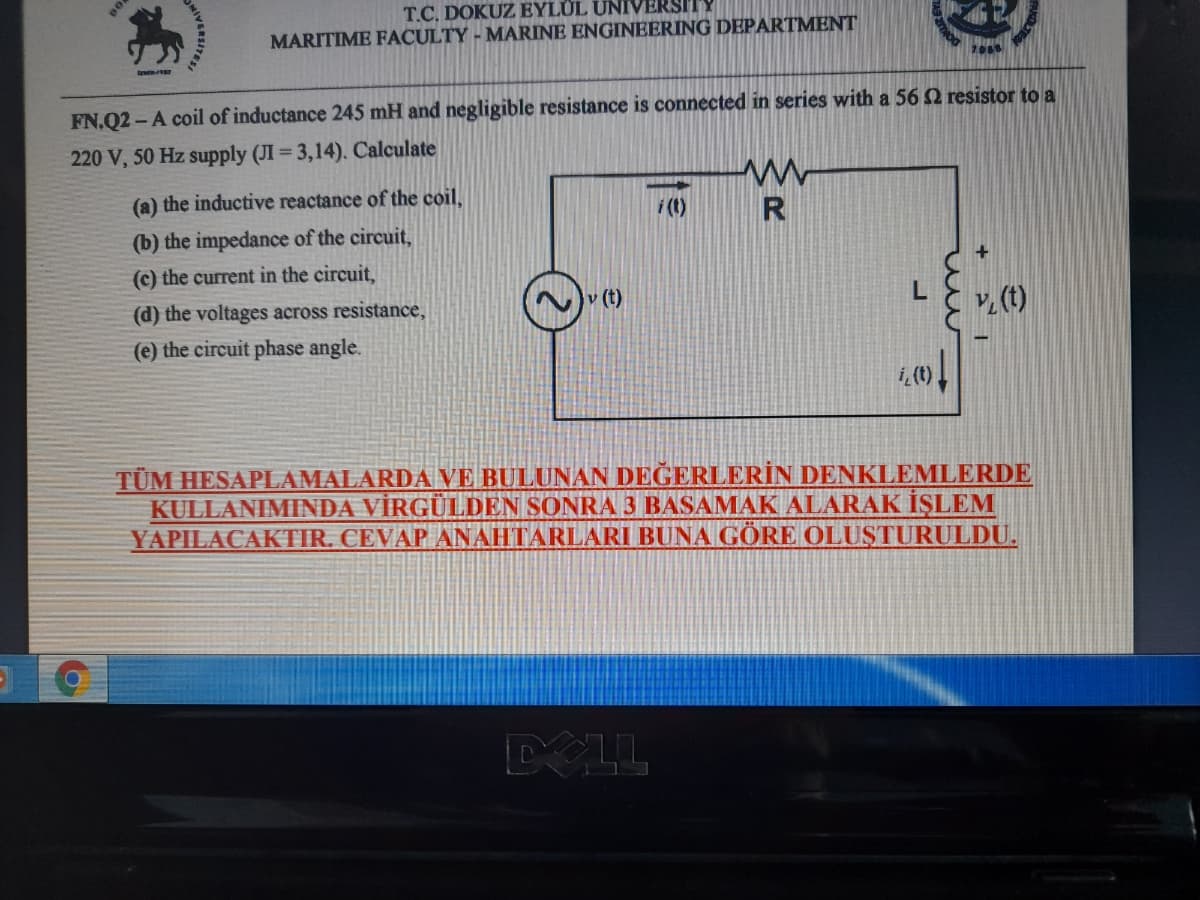
FN.Q2 - A coil of inductance 245 mH and negligible resistance is connected in series with a 56 2 resistor to a 220 V, 50 Hz supply (JI = 3,14). Calculate (a) the inductive reactance of the coil, i (1) R (b) the impedance of the circuit, (c) the current in the circuit, (d) the voltages across resistance, (t) v (t) (e) the circuit phase angle.
Q: a. Find the power delivered to an element at t = 30s if the current entering its positive terminals…
A: As per our guidelines we are supposed to answer only one question. Kindly repost other questions as…
Q: Three coils each having resistance 62 and inductance LH are connected in delta, to a 415 V, 50 Hz,…
A:
Q: EX4: (H.W) A single-phase half wave a.c voltage controller as shown in Fig. below, has a resistance…
A: resistance =5 ohm voltage=120v frequency=60hz
Q: Consider the resistor circuit shown in Fig. 3, and calculate the Thévenin equivalent circuit between…
A: In this question, Find the Thevenin voltage across the terminal x and y in the time domain.
Q: Problem 1: For the system shown below. 4 cos(2m 1000 t) 10 cos(2n 100, 10 cos(2 10,000 t) A. Find…
A:
Q: 1. Determine v(t) and i(t) in fig Ex 1. Use phasor and then time domain form. 2. A current source in…
A: In this question, RL circuit is given Find the current and voltage as shown in the circuit using…
Q: An iron ring 20 cm mean radius is made of square of iron of 3 cm × 3 cm cross-section and is…
A:
Q: A wind turbine is installed, the speed of the wind is 9.6 m/s, the pressure is 1 atm and the…
A: For the given data wind power density is determined as shown below
Q: Two magnetically coupled coils have self-inductances of 60 mH and 9.6 mH, respectively. The mutual…
A: (1) The mutual induce inductance (M) for two coils L1 and L2 is: Where, The coefficient of mutual…
Q: The voltage and current at the terminals of the circuit element in Fig. 1.5 are zero for t < 0. For…
A: The Power is calculated by: P=VI Given in Question: V=400e-100tsin200t VI=5e-100tsin200t A
Q: *A coil takes a current of 10 A of 0.76 pf from 250 V, 60 Hz source. If the coil is used temporarily…
A:
Q: 1.5kQ 50mH 20µF Vin 5 Vpk 50 Hz 0° Figure 2 Discussion: Q2\ For the circuit in fig. (2) Change the…
A: Given circuit consists of resistor, inductor and capacitor in series. The frequency of supply is…
Q: The chopper shown in Fig. 2(a) is connected to a 2000 V dc source, Es, and the load resistor, Ro,…
A:
Q: Find the value of the resistance R and inductance L which when connected in parallel will take the…
A: In this question, A resistance R1 and L1 are connected in series. If they will be connected in…
Q: fuel power plants? 2) There is a mono-crystal Si photovoltaic panel (size: 80 cm x 60 cm). 88% of…
A: Since you have posted a question with multiple sub-parts, we will solve first three subparts for…
Q: A 3 phase, 50Hz, Two bus, single transmission line power system consisting of line series resistance…
A: In this question series resistance inductance and shunt capacitance are given. so this is a medium…
Q: PROBLEM 4: In the circuit shown, 2.5 N b + 4.5 V| a 6.2 V+ Determine the following: A. Magnitude and…
A:
Q: Short Problem: Given a parallel RLC circuit comprised of the following element: 61.64-ohm resistor,…
A: In this question we need to find a absolute reactive power of the given circuit.
Q: 4. Two magnetically coupled coils have self-inductances of 60mH and 9.6mH, respectively.The mutual…
A: Part (A):- The given two magnetically coupled coils have self-inductance of 60mH and 9.6mH…
Q: i(t) 20 2 v(t)=Vmcos(1200t - 10°) 40 mH 20 µF
A:
Q: FN.Q2-A coil of inductance 245 mH and negligible resistance is connected in series with a 56 2…
A: Given that V= 220v V= 220<0° f= 50 Hz L = 245 mH R= 56 ohm
Q: A conducting coil, with current i(t) = 4.40e−0.0250t sin(120πt), with i in amperes and t in seconds,…
A: The current flowing through the coil is given as Differentiating the current i(t) with respect to…
Q: The mutual inductance and self-inductances of the coils shown are M=40 mH, L1=25 mH, and L2=100 mH.…
A: 1: The relation of coupling coefficient (k) with mutual-inductance and self-inductance is given by:…
Q: uestion -10 PMMC instruments has a coil of dimensions 12 mm × 10 mm. The flux nsity in the air gap…
A:
Q: 10. A 20 µF in an audio amplifier circuit produces a voltage drop of 5V at 1 2 points kHz. Find the…
A:
Q: uctor voltage, which is left as an exercise for the reader. 1 kN PRACTICE 10.3 Let v, = 40 cos 8000t…
A: Given circuit in time domain is, Convert the time domain circuit into frequency domain: Given…
Q: 2. Two coupled coils have inductance of L1 = 0.8 H and L2 = 0.2 H, respectively. If the coefficient…
A:
Q: Two admittances, YA = 0.3 + j0.4 and YB = 0.2 – jo.25, are %3D | connected in parallel. If the…
A: current = voltage*admittance. if teo admittances Y1 and Y2 are connected in parallel then…
Q: Electrical Engineering A cylindrical hollow pipe is made of steel (μr = 180 and σ = 4 x10^6 S/m).…
A: Intrinsic impedance is the characteristic impedance whose value is equal to the ratio of magnetic…
Q: Vs m 0.5 H M m 1 H 25 mF 12 www 5Ω
A:
Q: An enterprise with a supply voltage of 220/380 V consumes 350 kW of active power under a power…
A:
Q: 1. 24 Volt battery is supplying series connected RC load through a diode. R= 1 Ohm C= 500…
A:
Q: Electrical AC circuit is given in Fig.1. Please derive the expression of the instantaneous current…
A:
Q: Fig. 1 Fig. 2 2. An air cored coil of inductance L=3H is supplied by a DC voltage source, Fig.2, and…
A: Emf induced across the coil or inductor is E = L * dI/dt
Q: F1 T1 RL 400 1_AMP V1 5:1 40Vpk 60HZ 0, Using the circuit above, solve for the following: Secondary…
A:
Q: Q#01) Analyze the circuit given below. Given Data: Rs=1.5 KQ , R1=40KO, R2=10KN, Rc=6.8KN, Rɛ=2KQ,…
A: Given RS=1.5kΩR1=40 kΩR2=10 kΩRC=6.8kΩRE=2 kΩβ=100VCC=20 VVSp=100 mVfi=1.5kHz where…
Q: Problem 1 t=0 The circuit has been running for a long time prior to the switch 50 Ω closing at t=0.…
A:
Q: Two identical coils, each of 25 2 resistance, are mounted coaxially a short distance apart. When o…
A:
Q: Given a series circuit consisting of a DC voltage source, resistor, capacitor, inductor, and switch…
A: The given problem is transient analysis of RLC circuit with DC supply. To solve these type problems…
Q: Electrical Current The current I in a circuit with voltage E, resistance R, capaci- tive reactance…
A: According to the given parameters and instructions in the question, it is required to calculate the…
Q: MARITIME F EN.Q2- A coil of inductance 245 mH and negligible resistance is connected in series with…
A: Given : Note : It is the kind notice that according to the guidelines of a company we supposed…
Q: 1. An electrical circuit consist of a series connected resistor (100 ohms) and a coil with…
A: In this question, We need to calculate the current in the circuit after t= 2s. If An electrical…
Q: MISCELLANEOUS PROBLEMS FOR PRACTICE 25. A coil, of resistance R and inductance L, is connected in…
A:
Q: Problem: Given a parallel RLC circuit comprised of the following element: 97.19-ohm resistor, ideal…
A: First we will find out the current then power .
Q: Q.decide if the given statement is true or false,and give a brief justification for your answer.If…
A: Given- Voltage, E(t)= E0 cosωt Frequency, ω = 1 /√LC To find- Steady-state current of maximum…
Q: Q2) An AC inductive load of 120KW, 150KVAR supplied by voltage source of 500V. If a capacitor of…
A: The solution can be achieved as follows.
Q: Q2-A coil, having a resistance of 15 N and an inductance of 0.75 H, is connected in series with a…
A:
Q: 1. In the electric network of Fig. 86, E = 60 volts. Determine the currents I, and I, as functions…
A:
Step by step
Solved in 2 steps
- The mutual inductance and self-inductances of the coils shown are M=40 mH, L1=25 mH, and L2=100 mH. 1. Calculate the coupling coefficient. 2. Calculate the energy stored in the coupled coils when i1=10 A and i2=15 A 3. If the coupling coefficient is increased to 1 and i1=10 A, what value of i2 results in zero stored energy?TOPIC: Transmission Lines, Power Systems, and Powerplants:INSTRUCTIONS:- Answer in this format: Given, Illustration, Required Conversion, Solution, Final Answer.- Step-by-step solution, do not skip even simple calculations to avoid confusion.- If answered in written form, make sure it is readable.PROBLEM:A three-phase, three-wire, 500-V, 60-Hz source supplies a three-phase induction motor, a wye-connected capacitor bank that draws 2 KVAr per phase, and a balanced three-phase heater that draws a total of 10 kW. The induction motor is operating at its rated 75 Hp and has an efficiency and power factor of 90.5 and 89.5 percent, respectively. Determine the system KVA. 78.12 75.98 24.81 83.17Two coupled coils have inductance of L1 = 0.8 H and L2 = 0.2 H, respectively. If the coefficient of coupling is 0.75, find the turns ratio N1/N2 for the coils. Show Solution Please
- The feeder is to be used with an antenna for which an inductive reactance is measured as j60 Ohms at 1.7 MHz. The resistive part of the antenna’s impedance is measured as 80 Ohms. Using the online impedance matching calculator, design a suitable impedance-matching network for each of the two cables if the coaxial cable has a characteristic impedance of 75 Ohms and the twin lead cable has a characteristic impedance of 300 Ohms, so that the inductance is in the longitudinal branch, while the capacitor is in the transversal branch of the impedance matching network. Do not round the resulting values.Given the following characteristic equation: 1+K/S(S2+2S2+8S+5)=0 (a) Using Routh method determine the range of K for which this closed loop system is stable. (b) Find the value of K for which the system has purely imaginary roots and determine the corresponding frequency of oscillations.Consider a PV module with the following external parameters at STC: Pmax = 320 W, VOC = 45 V, ISC = 8 A, NOCT =40 °C and the temperature coefficient of power is −1 W/°C. a) If the ambient temperature rises to 35 °C while the irradiance is 1,000 W/m2, what is the cell leveltemperature, calculated with the NOCT model?b) What is the new power output of the PV module under the new ambient temperature of 35 °C and 1,000W/m2irradiance?
- An air-cored choking coil is subjected to an alternating voltage of 100 V. The current taken is 0.1 A and the power factor 0.2 when the frequency is 50 Hz. Find the capacitance which, if placed in parallel with the coil, will cause the main current to be a minimum. What will be the impedance of this parallel combination (a) for currents of frequency 50 (b) for currents of frequency 40?The resistance and inductance of a coil can be obtained by connecting the coil in series with a known resistance R and measuring the coil voltage Vcoil, the resistor voltage VR and the total voltage V. The frequency must also be known, but the phase angles of the voltages are not known. Given that f = 60Hz , R = 10 ohm Vcoil = 22.4 V. VR = 20 V and v = 36v , find the resistance and inductance of the coil.The transformer in the circuit shown in Fig. 1(a) is an ideal transformer with a=1/3. The circuit is supplied from a sinusoidal ac source with a frequency 60 Hz. Determine the angular speed ω. Determine the source voltage RMS value. Express the supply voltage as a function of time. Calculate the load resistance value (9 Ω) referred to the transformer low voltage side. Calculate the circuit equivalent resistance as seen by the source. Calculate the current drawn from the supply. Calculate the load voltage Vo. Calculate the power dissipated in the 3 Ω resistor. Draw, to scale, the phasor diagram including: supply voltage, supply current, load voltage and load current.
- Consider the load convention that is used for the RLC elements shown in Figure 2.2 of the text. A. If one says that an inductor absorbs zero real power and positive reactive power. is it (a) True (b) False B. If one says that a capacitor absorbs zero real power and negative reactive power (or delivers positive reactive power), is it (a) False (b) True C. If one says that a (positive-valued) resistor absorbs (positive) real power and zero reactive power, is it (a) True (b) FalseA coil of inductance 318.3 mH and neg[1]ligible resistance is connected in series with a 200 resistor to a 240V, 50 Hz supply. Calculate (a) the inductive reactance of the coil, (b) the impedance of the circuit, (c) the current in the circuit, (d) the p.d. across each component, and (e) the circuit phase angleA resistor of 50 ohms, a 200mH inductor, and a 1.5 x 10⁻⁴ F capacitor is connected in parallel to a 120-volt, 60 cps source. Calculate: a) the equivalent impedance b) the current in each load c) total current d) the total real, reactive, and apparent powers e) power factor.