For the bar in the way the loading status is seen determine the strain energy on the rod so that the shear stress on the rod is maximum 120 MPa.( Part of BC is hollow)
For the bar in the way the loading status is seen determine the strain energy on the rod so that the shear stress on the rod is maximum 120 MPa.( Part of BC is hollow)

Mechanics of Materials (MindTap Course List)
9th Edition
ISBN:9781337093347
Author:Barry J. Goodno, James M. Gere
Publisher:Barry J. Goodno, James M. Gere
Chapter5: Stresses In Beams (basic Topics)
Section: Chapter Questions
Problem 5.9.3P: A vertical pole consisting of a circular tube of outer diameter 5 in. and inner diameter 4.5 in. is...

Related questions
Question
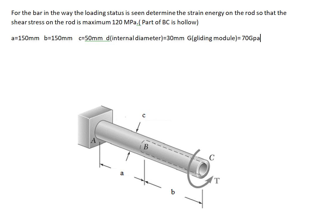
Transcribed Image Text:For the bar in the way the loading status is seen determine the strain energy on the rod so that the
shear stress on the rod is maximum 120 MPa.( Part of BC is hollow)
Expert Solution
This question has been solved!
Explore an expertly crafted, step-by-step solution for a thorough understanding of key concepts.

Step by step
Solved in 2 steps with 5 images

Knowledge Booster


Learn more about
Need a deep-dive on the concept behind this application? Look no further. Learn more about this topic, mechanical-engineering and related others by exploring similar questions and additional content below.Recommended textbooks for you
Mechanics of Materials (MindTap Course List)
Mechanical Engineering
ISBN:
9781337093347
Author:
Barry J. Goodno, James M. Gere
Publisher:
Cengage Learning
Mechanics of Materials (MindTap Course List)
Mechanical Engineering
ISBN:
9781337093347
Author:
Barry J. Goodno, James M. Gere
Publisher:
Cengage Learning